I believe that Aza’s config file is for a canbus setup, right? I am not using canbus on my printer.
1 Like
Thanks for this Aza. After looking through each one of them, it appears everyone is running a Manta M8P board and/or running a canbus system. I would be looking for an SKR Pro V1.2 without canbus.
Is it a simple edit to switch the config from Manta M8P to Skr Pro? I am not familiar with the pin mappings.
1 Like
Get a copy of the skr board pinout (google image search) and change the pin names to match and delete the can bus reference. If you get it wrong, when it tries to load it will tell you where the problem is and you just edit and click restart. It was a little intimidating at first, but is really straight forward. I learned a lot from voron documentation and klipper docs.
Thanks. I will try this. I also notice in @Jonathjon ‘s V4 Klipper config that there are UART pins. When originally setting this machine up for Marlin, I had bent the UART pins down on the TMC2209. Do I need to utilize those pins now?
I’d just comment it out and restart.
When I first setup Klipper on my smaller printer, I did a lot of ‘comment this out for now’ type programming. Very little of it did I go back and try to figure out later.
Start with the basics. Get the printer moving. Then get the bed, hotend, and fans turned on. Then get the extruder turning.
I’ll be doing this as well in the near future. I keep running into features of Klipper that I want on my MP3DPV4 that I don’t have in Marlin. Plus I find Klipper easier to work with.
1 Like
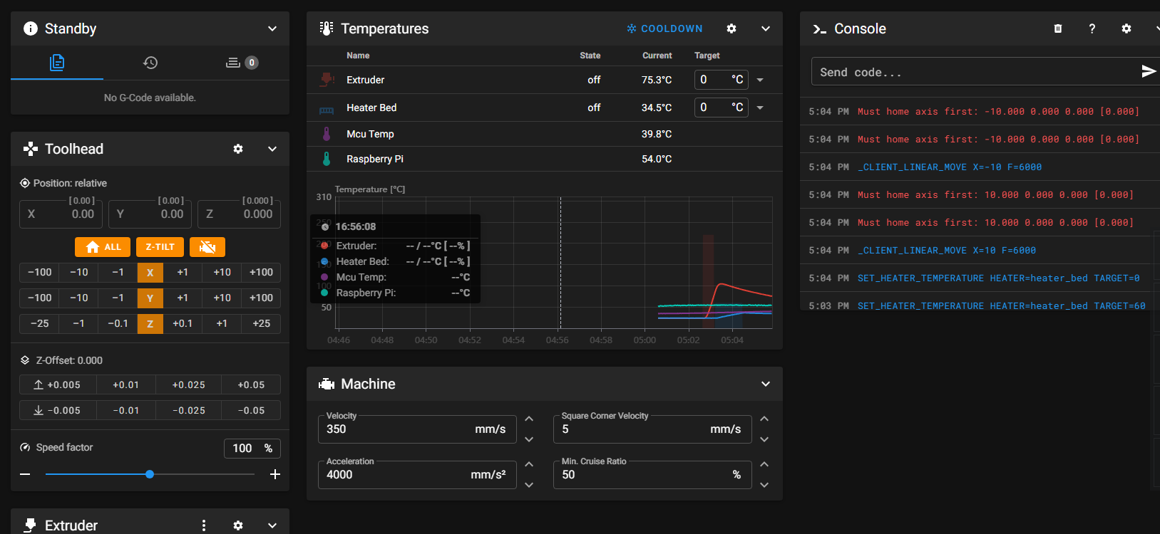
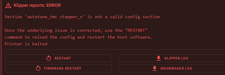
Okay I am connected (corrected all the errors). The bed heater and hotend are working. I tried to move the machine and it needs to home first. I tried to home it and nothing moved.
Safe to assume my pin assignments are not correct?
1 Like
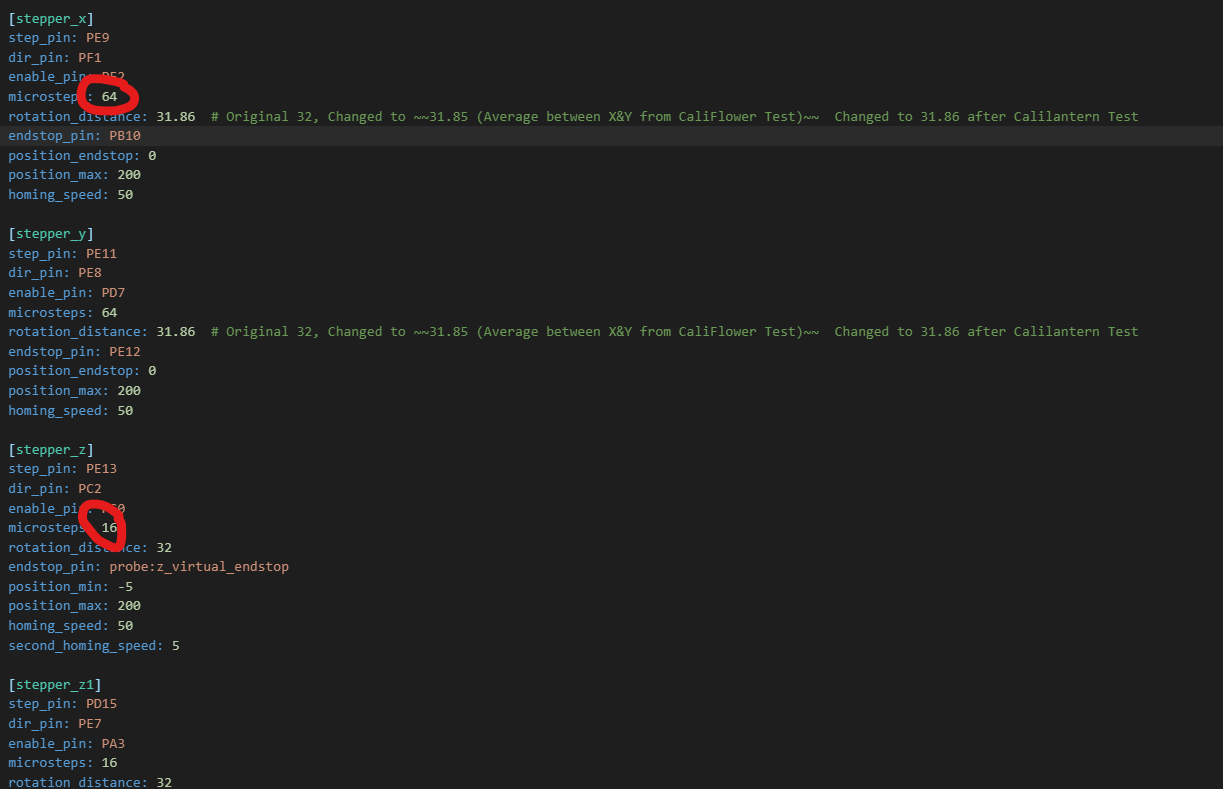
I notice different microstep settings as well. I remember from before that there are switches underneath the motor drivers where you can set the correct microstep. Do those switches need to be adjusted to match the microstep in config file for any reason?
I am getting no communication with the steppers or the endstops. I did QUERY_ENDSTOPS and was not getting any feedback. I feel confident that my pin assignments are correct. I think.
printer.zip (8.3 KB)
My modified config file attached here, if needed.
looks like you are making good progress.
My skr board assignments are like this:
# basic printer style layout
[printer]
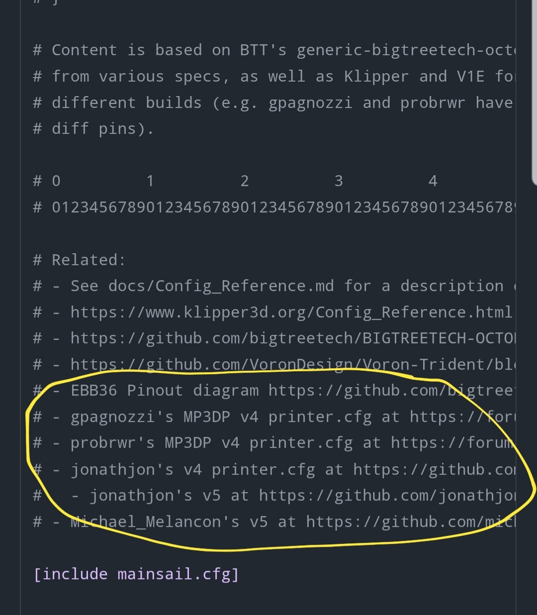
# Related
kinematics: corexy
max_velocity: 600 # default: 300
max_accel: 3500 #AZA default: 3000
max_z_velocity: 300 # default: 5
max_z_accel: 300 # default: 100
square_corner_velocity: 5 # set to default of 5 for input shaping
########################################
# TMC2209 configuration
# - Set uart_pin to CS pin, per pinout diag
########################################
[tmc2209 extruder]
uart_pin: PD6
run_current: 0.8
#hold_current: 0.4
stealthchop_threshold: 0 #999999
[tmc2209 stepper_x]
uart_pin: PC13
#diag_pin: PG6
run_current: 0.9
#hold_current: 0.4
interpolate: False #AZA Why??? Default True, but gpagnozzi False (note his is Manta M8P not Octopus), see https://www.klipper3d.org/Config_Reference.html?h=pixel#tmc2209 and https://forum.v1e.com/t/mp3dp-v4-build-sw-virginia/37238/31?u=azab2c
stealthchop_threshold: 0 #999999
[tmc2209 stepper_y]
uart_pin: PE3
#diag_pin: PG9
run_current: 0.9
#hold_current: 0.4
interpolate: False
stealthchop_threshold: 0 # 999999
[tmc2209 stepper_z]
uart_pin: PE1
#diag_pin: PG10
run_current: 0.8
#hold_current: 0.4
interpolate: False
stealthchop_threshold: 0 #999999
[tmc2209 stepper_z1]
uart_pin: PD4
#diag_pin: PG11
run_current: 0.8
#hold_current: 0.4
interpolate: False
stealthchop_threshold: 0 #999999
[tmc2209 stepper_z2]
uart_pin: PD1
#diag_pin: PG12
run_current: 0.8
#hold_current: 0.4
interpolate: False
stealthchop_threshold: 0 #999999
# driver 5 : uart_pin: PE4
# driver 6 : uart_pin: PE1
# driver 7 : PD3
###############################################################################################################################################
# motor definitions
################################################
# Driver0 This is the B motor on the left side
[stepper_x]
enable_pin: !PF2
step_pin: PE9
dir_pin: !PF1
endstop_pin: PB10 ##carriage trigger
microsteps: 16
rotation_distance: 32
position_endstop: -5
position_max: 205
position_min: -5.0
homing_speed: 100
second_homing_speed: 3
# Driver1 this is the A motor on the right side
[stepper_y]
enable_pin: !PD7
step_pin: PE11
dir_pin: !PE8
endstop_pin: PG9 #left motor
microsteps: 16
rotation_distance: 32
position_endstop: 205
position_max: 205
position_min: -5.0
homing_speed: 100
second_homing_speed: 3
## Driver2 for 1 of 3 z motors
#(front left)
[multi_pin z_enable]
# THIS IS IF you have a Z-brake relay . one pin is for the relay, one is for the z motor enable (likely PD8) just ignor the multipin calls and replace with PD8 if no brake system.
pins: !PC0, PD8
[stepper_z]
enable_pin: multi_pin:z_enable
step_pin: PE13
dir_pin: PC2
microsteps: 16
rotation_distance: 32
endstop_pin: probe:z_virtual_endstop
position_max: 400
position_min: -5.0
homing_speed: 50
second_homing_speed: 3
homing_retract_dist: 2
## Driver3 for 2 of 3 z motors
#(rear)
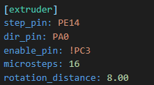
[stepper_z1]
enable_pin: !PC3
step_pin: PE14
dir_pin: !PA0
microsteps: 16
rotation_distance: 32
endstop_pin: probe:z_virtual_endstop
## Driver4 for 3 of 3 z motors
#(front right)
[stepper_z2]
enable_pin: !PA3
step_pin: PD15
dir_pin: PE7
microsteps: 16
rotation_distance: 32
endstop_pin: probe:z_virtual_endstop
#--------------------------------------------------
FYI: I don’t know if this is fully working yet, but the pins are correct.
to reverse a motor, add or remove the ! at the direction pin
Ahh! I forgot to include the ! on the enable pin assignments… I guess that is important.
So now my axes are moving in the correct direction but still not communication with endstops. Any tips there?
they are normally open endstops I believe. according to the photo:
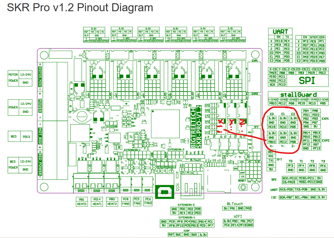
are they wired correctly?
I may have not wired mine in a standard fashion, so verify X, Y, Z E0, E1, E2 and how they correspond with X, Y Z axis endstops.
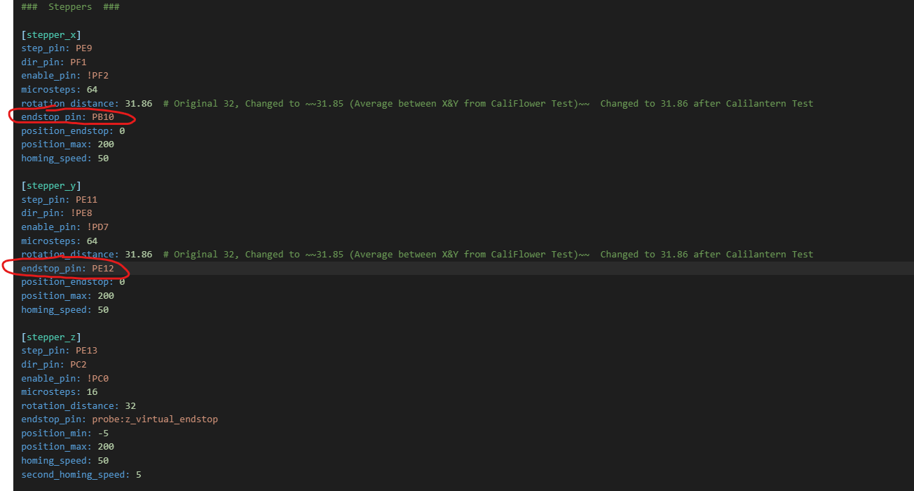
according to the board pinout diagram above,
X would be PB10
Y would be PE12
Z would be none because you use a BL touch… If you plug it in to the board header for it, the code for that is here:
[bltouch]
sensor_pin: ^PA2 # BLTouch Probing input signal pin (^ means pullup)
control_pin: PA1 # SERVO pwm output pin for pin movement
x_offset: -5 # measured offset for H2V2S and hot end fan mounted bl touch
y_offset: -20
keep in mind if you use a micro touch from BTT, then it won’t work unless powered from the power supply the USB doesn’t have the juice to run it and the board will act weird and brown out.
Alright, I’ve got everything working correctly now. I have successfully printed the 1st layer of a part. I stopped there because I quickly realized I have some tuning to do.
Thanks everyone for your help in getting me this far! I am enjoying Klipper much more than Marlin. Hopefully I can handle the tuning side of things and get it printing nicely.
Then… I will do it all over again to finish up the V5 build.
3 Likes
I feel like I am over-extruding now. When I was running Marlin, I had my flow ratio for PLA around 0.96. I am all the way down to 0.6 flow ratio while doing the tuning and it still seems to be too much.
Is it the steps/mm for the extruder? Is it something else config wise?
You should just be able to do the 100mm extrusion test to see how close you are. From there, there are test prints, if you want to get a little better.
1 Like
Doing this now. I extruded 100mm and it went waaayyyyy past the 100mm mark. Clearly not right there. However, in the config, it is not steps/mm. It is set to 16 microsteps for the extruder. Should I try 32 and 64?
EDIT: Nevermind.. I see it is rotatation_distance in Klipper.
2 Likes
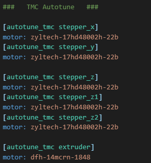
Getting ready to do this calibration myself, maybe tonight after work. I wish I could find someone who’d published a “close enough” starting point for the extruder I bought from E3D but everyone says “don’t trust other people’s numbers.”
Dont trust. Verify. But as an iterative start, it doesnt hurt to have a number in the ballpark.
Google says for the roto
[extruder]
rotation_distance: 26.8937
gear_ratio: 11.262:1
microsteps: 16  # Check your TMC driver settings
full_steps_per_rotation: 400  # The Roto uses a 0.9°