Finished printing everything this week and finally dug up a metric countersink bit to do the baseplate! (who decided imperial countersinks should not be 45??)
I ordered it from sendcutsend before Cam was offering on the shop… I would not really recommend it, the stock is slightly warped and they told me they can’t offer any sort of spec on flatness, even just for bare sheet stock with no bends. Maybe the geometry of the plate can be changed to get more even thermal distribution during laser cutting to prevent warping (assuming the stock was flat going in…)
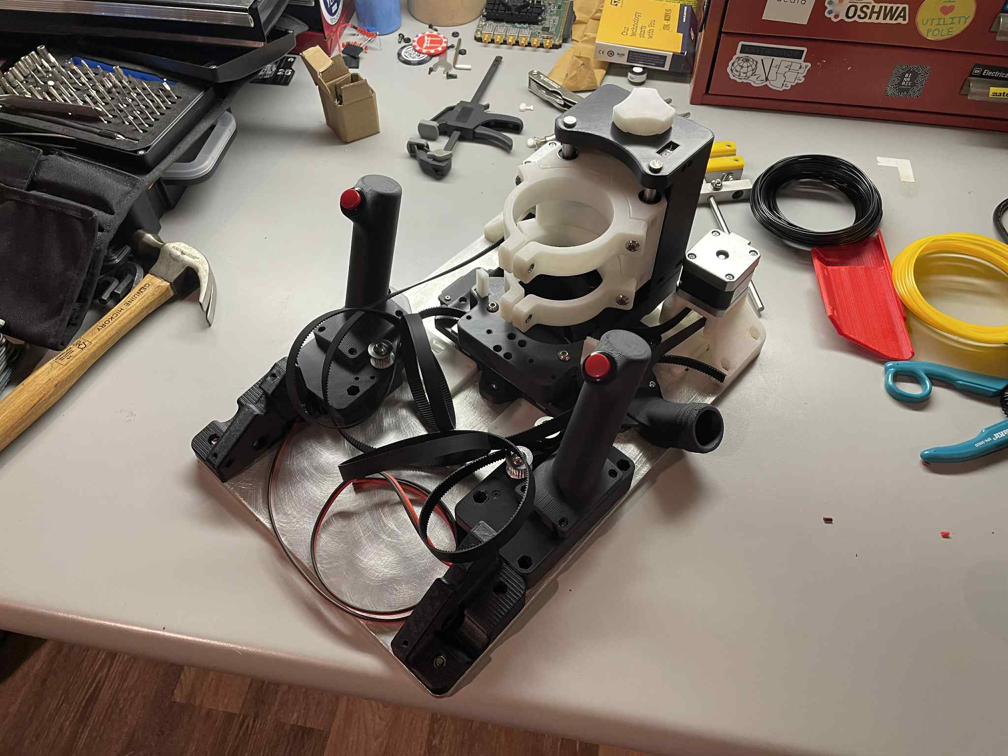
The belt tension system is genius, I never saw it before, it’s pretty clever! The only thing that tricked me is it requires making sure you install the belts with the correct twist in the line before bolting the linear top linear axis on. It might be nice if it could be changed to pockets on the top face so that you can run the belts after assembly. That, or stacking the axes so the twist is not needed. Also the 3D model has toothed idler near the belt tension slug, but there was no way to fit that into the part I printed, not sure if it’s an old rev or what. I just installed an M5 bolt and ran the belt across it.
Almost all pieces fit on my V0 printer, it’s a nice surprise (excludes baseStage, vacMount, xStagePlate, yStagePlate)! Otherwise all parts can fit/be printed on Prusa mini that I had access to at work.
Rather than going with 80mm lead screw + spider coupler, I just got a stepper with 100mm integrated leadscrew. This makes assembly slightly annoying but for the most part is pretty painless and very easy to source. I don’t have tools to cut the leadscrew to 80mm. The same for the guide rails, going with a standard size for the design (100 or 150mm) might be more kit-friendly as sourcing 120mm is a bit unusual ( I found 125mm on aliexpress, you can see them sticking out the top slightly ). There is room for anti-backlash nuts on the Z axis, this helped with some slop I was seeing, but I guess this would not be very apparent in regular use, maybe only visible when doing height contour work). I have all the electronics other than the custom PCBs so just waiting on those in the mail now! So far a very easy build, even without much documentation - the design speaks for itself in many ways. A lot of the parts really are designed very well for printing, I love the symmetry and ease of assembly so far.
Awesome!! Sorry been MIA this weekend, but I’ve been chugging away at the build instructions and finally got them finished (just in time for you to be nearly done lol):
Actually, you can do all the belt routing after everything is assembled hehehe . You can feed the belt in from the side.
Hmm how long are your toothed idlers? The spec’d idlers are 18mm long. Someone else mentioned accidentally ordering 20mm long ones, which frustratingly don’t fit.
Super valid. Wouldn’t be the worst thing in the world to go with 150mm in the future and just have a bit more Z travel.
So glad to hear!! Hope you can still gain some things from the instructions.
I discovered this later when I put the wrong twist in the belt and didn’t want to take everything back apart
I think I missed the ones with different diameter - I only had the larger drive pulleys and they didn’t fit. Considering this part doesn’t move after assembly/tensioning, did you consider just adding the radius as part of the 3D print rather than an installed idler? edit: This seems like a very large quality of life feature during tensioning, so it’s a good call to keep them, sorry for detracting!
Just flipped through it - looks great! I’ll need it when assembling the sensors after I get the PCBs!
Have you had issues with the locknuts spinning in the print(s)? For me I tried to remove some parts after assembly and it was pretty tricky - the locknut torque seems higher than the holding torque of the plastic It could very well be my printer is not tuned quite right and the holes for them are too large…
I don’t know, I got some T8 POM ones and they don’t feel any worse than the regular nut… but it did help with some slop in engagement when changing directions by hand. I got the type with the spring, not the set-screw/openbeam style (those definitely look like they would bind…)
As in essentially 3D printing the idler instead? I considered this, but eventually decided using the idler would be easier/cleaner.
I have had issue only when they are not properly seated. In normal conditions the locknut torque seems to be well within the capabilities of the plastic. It’s very possible the prints could use some tuning to make it easier for the locknuts to seat properly
Nope. That is experience from the LR, but I am talking about the compass.
Did you have the router installed? I would guess that holds it at the bottom end of the backlash all the time.
As I always say. “It is your machine”. I don’t mean that as a threat. You can and should do whatever you want with it. I just know we have had more trouble than benefit from those in the other CNC machines we talk about here. The T8 has plenty of torque to lift a big router. But friction is a problem, especially at higher feedrates.