Btw the stock marlin is a modified version of marlin, so that might be a reason. Modified as in somewhat proprietary. Ill try with the original marlin once im back!
In case i need to change the board, what do you think about this one?
This would work with a probe and also an end effector and all the jazz correct?
There also this one but it will be less powerful i guess, I dont mind spending the extra money to get a mega
EDIT 1:
Or I could go for this and a more “reputable” mega board like from elegoo
If Marlin doesn’t have a z probe configured, it will not understand G38.
My guess is that means it is working correctly. Unless I am mistaken, uCNC doesn’t do anything for the screen, so the previous firmware was writing stuff like 100% and then the uCNC firmware started and sent nothing.
I don’t think uCNC uses G28. It would be $H or something, right? The grbl and Marlin worlds are pretty separate on a lot of this stuff.
Regardless, the uCNC firmware should be spewing status messages occasionally. So it is either not running, or it is not connected.
Did you have to change the baud rate? The Marlin we use has it set to 115200. I am not sure what is used in uCNC.
I may be overly cautious here, but I would not recommend that for a beginner like this. It would not break anything, but being miles from help and changing the bootloader is not something I would recommend. It would take a good bootloader reflash to get it back to the starting point, compared to the relatively easy method of flashing over the bootloader you’ve been trying so far. The bootloader is a nice safety net for beginners.
Both µCNC and Grbl support G28 but they work has stated in the GCode standards document. The G28 is return to home…But this is an absolute position on the machine. Actually there are 2 home positions G28 and G30. this means the machine will go to that (absolute) position (directly or indirectly if X, Y, Z is specified).
Yes OpenCNCPilot and all other Grbl talking programs poll the status of the board several times per second. In the case of Grbl and µCNC is by sending a ? char.
µCNC by default if configured to work at the same baudrate has Grbl. 115200. Has stated. µCNC “talks” exactly the same language as Grbl (almost 100% except for a couple of non vital Grbl style commands like $I that outputs the compilation info and $S that puts Grbl to sleep. µCNC also has a couple of these commands that Grbl does not have like $P to ouput pin state). If you swap one firmware by the other the PC program should talk to both the same way.
Agree on that. For unexperienced users it can be tricky. Even for experienced ones sometimes…That’s why I said not to risk it if not confortable).
This one can also run Marlin. Doubt it would be able to cope with your printer LCD and other stuff…but it would run plugged to the PC via USB. So you would kind of have an extra spare board. This is and 8-bit microcontroller @16Mhz (or 20Mhz not sure now). It does not compare to yours.
This would be able to run it but it would be in the absolute limit of it’s capabilities, and by switching a few configurations on µCNC to make it fit…The processing power is about the same has the other but the available RAM and FLASH is veryyyy limited.
And maybe this Arduino Zero clone would pair better. The only thing you would have to make sure is that the shield is 3.3V ready or the 12V~24V rail for the stepper drivers does not feed any voltage regulator and is completely isolated.
But before going out to buy stuff give me a couple of days to see if I can figure out the issue with the bootloader.
Back on it, tried again to reconnect with your bin loaded but to no avail.
No green messages on the bottom right
Tried to send a ? through the “Manual” tab on the left but nothing happens. $P also doesn’t do anything.
Tried my last custom Marlin firmware to see what would happen in OpenCNCPilot, G28 doesnt work (it did in the stock firmware) odd. ? also doesnt work but that was expected.
In regards to board swaps, found a local reputable robot shop with lots of CNC stuff that sells a plethora of 32bit microcontrollers, if the need comes ill ask for your advice once again on the matter!
Ok. I’ve looked in the custom Marlin firmware and did not see anything special. I any case I copied the memory offset locations to the linker script file. I applied the latest patches and tested on my bluepill µCNC and all seems to run fine.
I’ve added a new branch with all these changes. You can get the new bin file here.
Try it out and let me know how it goes. If it works and it starts communicating and you’re still not comfortable with Grbl or configurations for your machine just don’t try to do any motions with it. I can help you with the next steps to get it moving.
Got on it, got the new bin, flashed it on the board but nothing happened in OpenCNCPilot, no green text on the bottom right, restarted the printer after the first flash and still no connection it seems…
Ok. I’ll do this. I’ll build you a New bin with a firmware that Will only blink a Led and se if it works and go from there…I’ll let you know when itvs done
Good news…The problem is probably in some kind of bug on my firmware and communications using USART3 (almost certain is a IO alternate function conflict). I’ll investigate and tell you something as soon has I figure it out.
EDIT: I already tried USART3 on my bluepill but it wasn’t sending text. I did the blinking test I told you earlied and didn’t work. I wrongly assumed the IO pin was dead…but it turns out it’s not…soo I’ll look in to it.
A bad bit mask. To setup IO pins inside SMT32F1 each GPIO port has 2x32bits configuration registers CRL and CRH. each register has a 4bit value to configure each pin (2 bits for mode and 2 for speed). This means CRL will configure pins 0 (0000 in binary) to 7(0111 in binary) and CRH will configure pins 8(1000 in binary) to 15(1111 in binary). You can see that 8 is in the same relative position (0) to CRH as 0 is to CRL (position 0). Registers 8 to 15 can be though like 8+(0 to 7). If you want the relative address in CRH of pin 10 you just mask the 4th bit by doing and AND operation 10(1010) AND 7 (0111) = 2 (0010). pin 10 is at position 2 of CRH.
well I don’t know why the hell the mask I was applying was 5 (101) and not 7(111). This made me unable to configure pins 10,11 and 14 and 15. It actually configured wrong pins.
This was an error I already fixed along time ago but I guessed from having several parallel branches it may have popped up again.
OK, tried the new bin file, same steps as the other times, nothing happened, no green messages on the bottom right… except for the windows sound of when you connect to a usb, which i believe didnt happen before.
when i turn the machine on or off it does that typical sound! dont know if it means much though…
EDIT 1: dont know if ill be reading the 1136 pages anytime soon
Ahh crackers… I was hoping this would BE the one. Ok so next will be the blinking Led. This Will at least give a clue if the firmware is running or not. I’ll let you know when I upload it.
Uploaded a new bin called Robin_nano_blink.bin.
This only initializes the MCU and blinks TX led every second. I’ve tested on bluepill and it’s running.
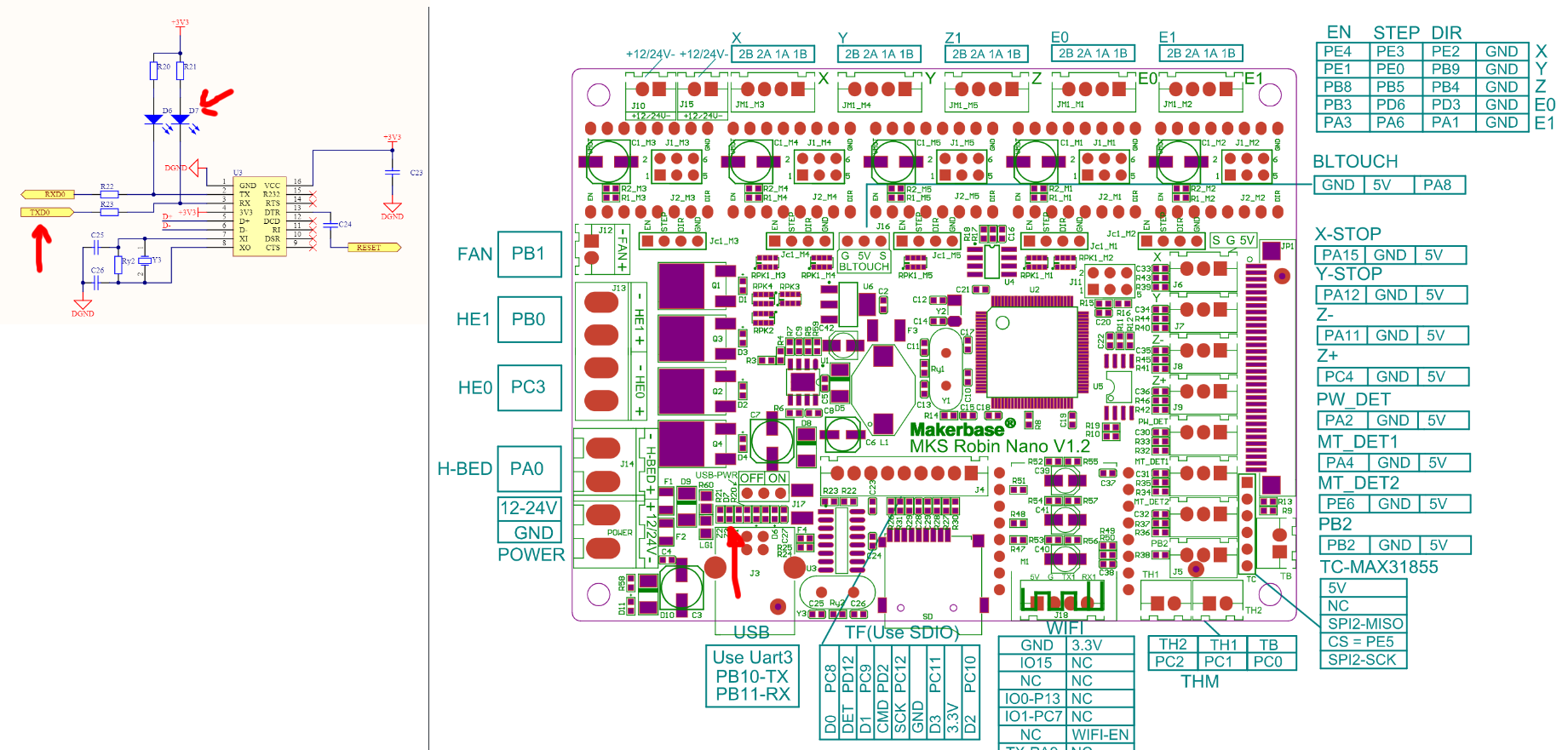
Here is your board schematic indicating the led that will blink.
I’ve also uploaded an alternative bin were the TX communications are done in a synchronous way. You can try that too although I’ll doubt it will do much difference.
EDIT: If the blink file doesn’t work then forget about it. Maybe there is something more that the bootloader expects before running the firmware (like a configuration file or something of the sort) and does not boot up because of that. This may be a wild idea but you can try and repeat the process with an empty Robin_nano_cfg.txt file to see if it works.
EDIT2:
I believe it always did the sound and you didn’t realized it. The USB protocol handling is done by the CH340 chip and it’s independent of the STM32F1 chip of your board. The CH340 acts as middle man creating a virtual serial port in USB and speaking to the hardware USART3 of your SM32F103VET6 chip. This removes all the USB handling hassle that is basically clock cycles wasted in protocols and uses the USART hardware that almost a fire and forget hardware implementation for transmitting data.
Ran the blink bin, tft uploading etc etc but no blinking, even when I try to connect with the pc.
Although I noticed where the arrow in the board schematic is pointed does not represent a LED on my board! ill upload a pic soon but its definetly not an led, its a resistor id say.
Also right aboce the arrow, USB PWR is on the off position, not sure if it would make a difference just a note.


 . I’ve replaced the bin. Try the new one (it’s in the same place and has the same name).