Manual Z-axis for cheap diode laser engravers and various laser modules

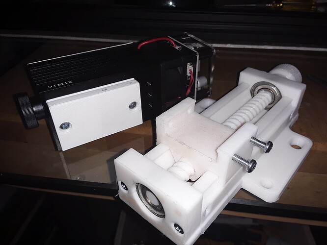
Recently, I presented a manual Z-axis that works quite nicely but is overkill for a light-weight laser module. And, as I discovered a couple of days ago, can be a pain to assemble when making another one if the printed fits are particularly tight. So I started looking to see what I could do to simplify assembly, make it more compact, and adaptable to various laser modules.

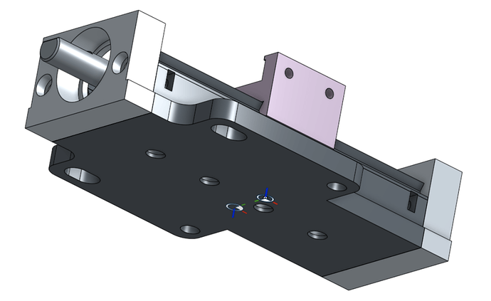
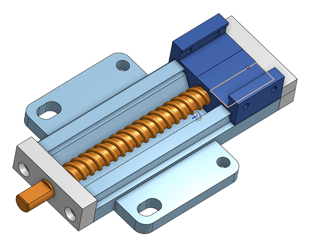
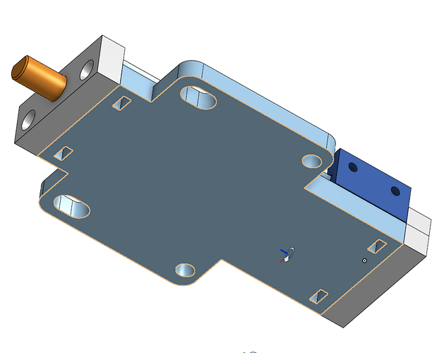
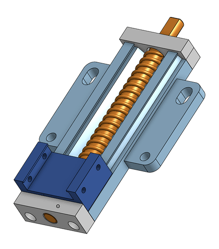
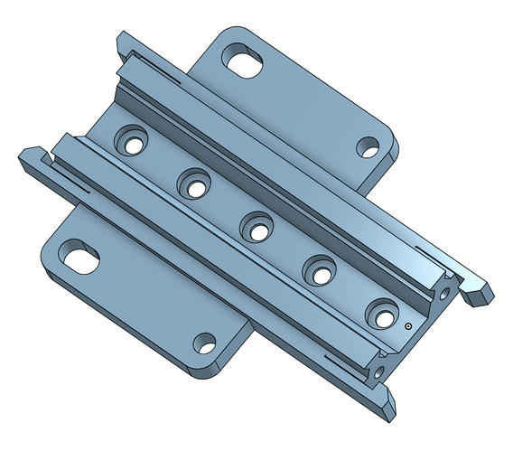
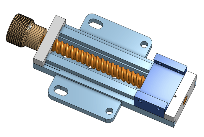
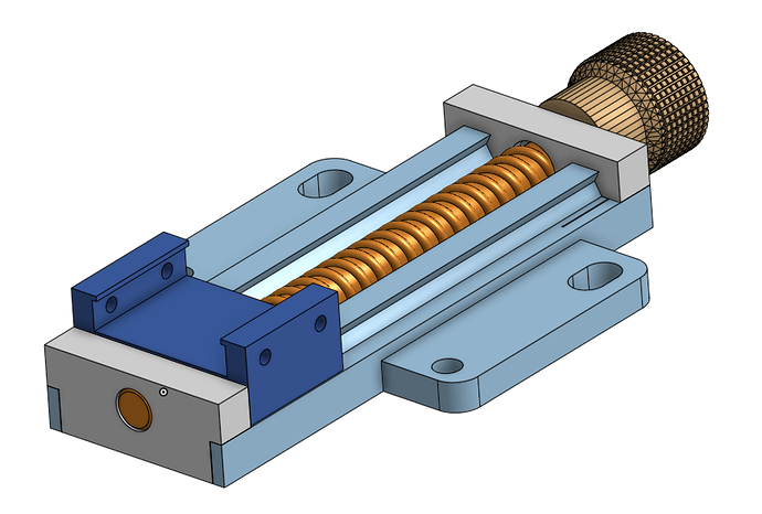
Firing up Onshape, I’ve come up with the following design…

It’s “mostly-printed” with only six printed parts, two 608 skate bearings, and six M3 machine screws/nuts… and is more compact while retaining the full 75mm of carriage travel of its predecessor.

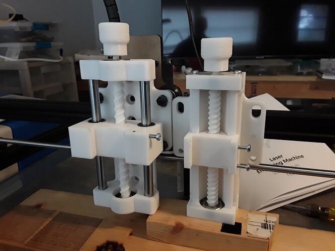
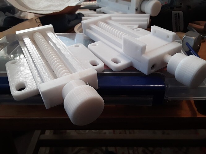
Previous design and new design side-by-side…

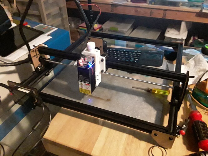
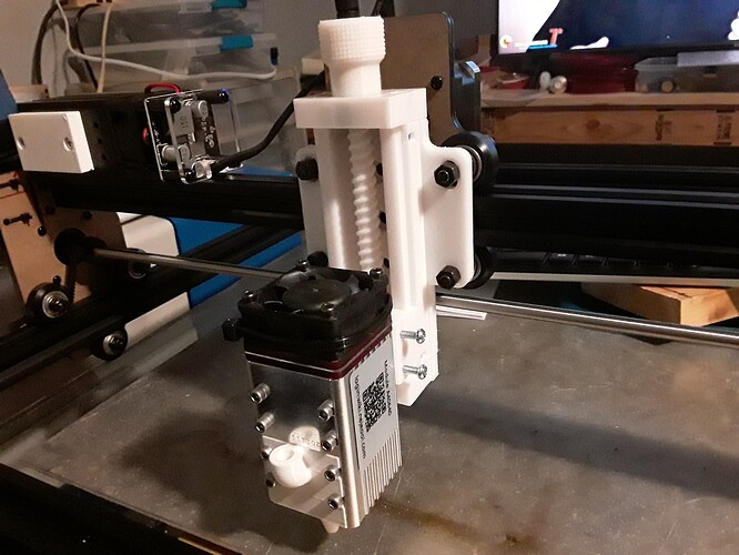
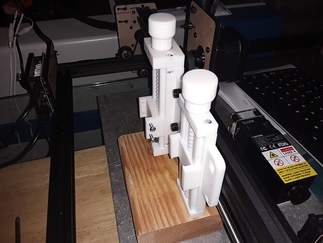
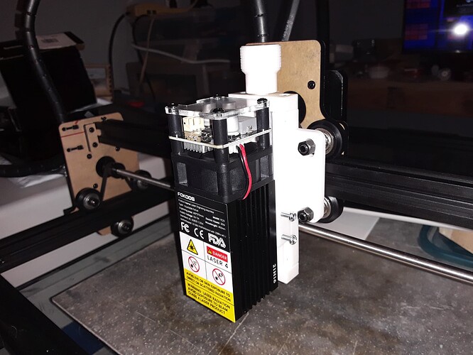
Cheap Fokoos engraver “in action” with new manual Z-axis…

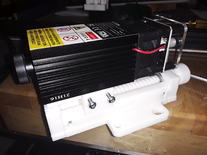
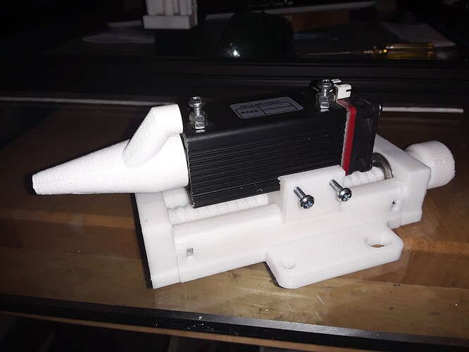
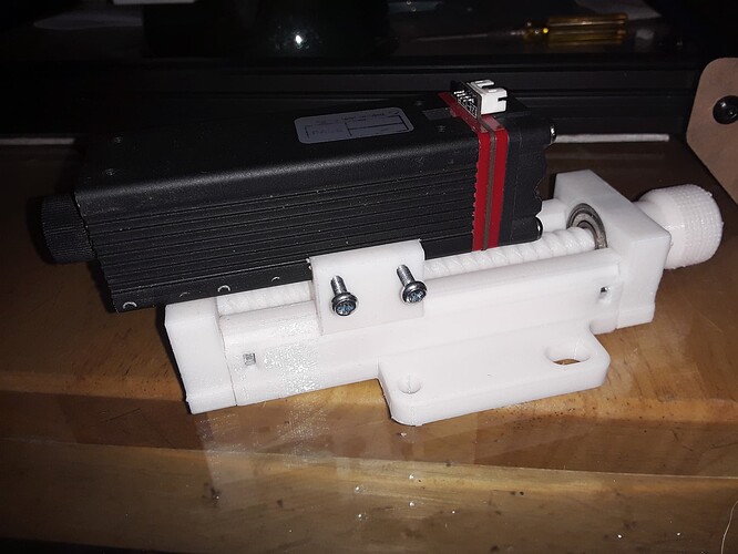
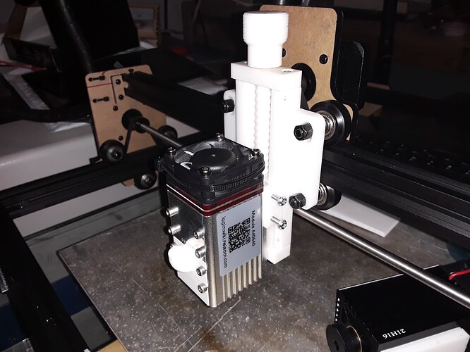
The carriage directly mounts any of the Neje laser modules and, with an easily-modified printed adapter plate, can be made to mount almost any laser module with a flat back and pattern of holes, as shown here…

A small Neje 2.5W(?) laser mounted…

and a larger/longer Neje 4W(?) laser…

and, finally, the popular Neje A40640 module that numerous of us are currently playing with…

I’ll put the design out on Thingiverse in the next day or two for those who are interested. I’ll include the adapter plate which can be easily modified to match the hole pattern on back of your laser module. Tinkercad, simple as it is, can actually be very handy for modifying existing STL’s and relocating/plugging holes to match what you need. Both the adapter plate and Z-axis backplate could be adjusted this way.

The purpose of this exercise is because I’ve found with the cheap laser engravers (Fokoos, Eleksmaker A3, etc) is that most don’t have, if at all, a very adjustable Z-axis mount and focusing the laser for different thickness materials can be a pain. They’ll recommend twisting the lens ring (as the one shown does) or loosening/tightening one or more screws on a small slide, etc… it also interferes with most air-assist assemblies you may be using. With this Z-design, the carriage slide allows the laser module to be located relative to the entire Z-assembly and then another fairly large range of motion is available relative to the material, by simply turning the knob/leadscrew to raise and lower the carriage and laser.

– David
22 Likes

I’ve published my design out on Thingiverse… here. It initially looked pretty good when first published but after going back in to edit a couple of things, it looked pretty crappy and incomplete after doing a “Save & View”. Holding my breath that it will straighten itself out with time… we’ll see. I’m really beginning to dislike Thingiverse… :face_with_raised_eyebrow:

3 Likes

I’ve found that TV updates your edits much faster for everyone else than it does for you. Probably also much faster than for anyone who looked at the thing before the edits. I think it’s basically browser caching that screws it up, but that’s just a theory. It seems to actually make your updates, it just won’t show them to YOU for a bit.

1 Like

I think you’re right. I just looked back and it’s a lot better. I’ve moved things around a little bit more, hopefully for a last time, and suspect it’ll be fine in a while. Thanks!

TV is honestly the worst. They really are way behind in everything but the number of models. Prusprinters.org is catching on.

4 Likes

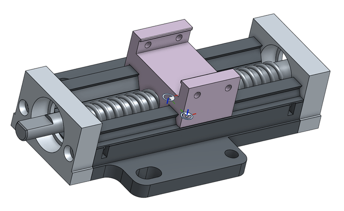
Apparently the cold has gotten to me and I’m not willing to leave well-enough alone. Normally a “don’t fix it if it ain’t broke” kinda guy it occurs to me that I wasn’t thinking this fully through. Having done away with the polished rods and linear bearings to simplify assembly, I was proud of myself. But, clearly, with all the plastic-on-plastic sliding surfaces in this thing, the roller bearings aren’t needed either. Shoot, this is a manually-adjusted mechanism designed to move at glacial speeds and carry negligible loads… and with no skate bearings, I should be able to make this thing thinner yet.

Back into Onshape…

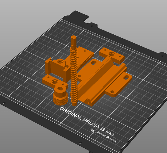
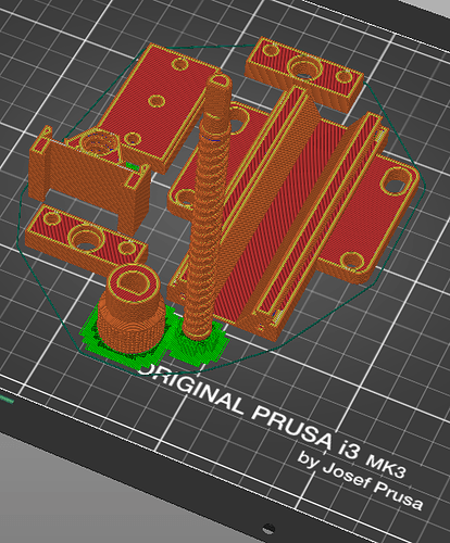
Then PrusaSlicer…

On to the printer and I should have something to play with this evening. It’s too cold to get out and frolic and carouse anyway… :wink:

– David
6 Likes

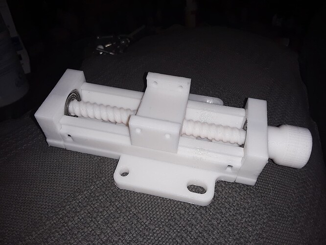
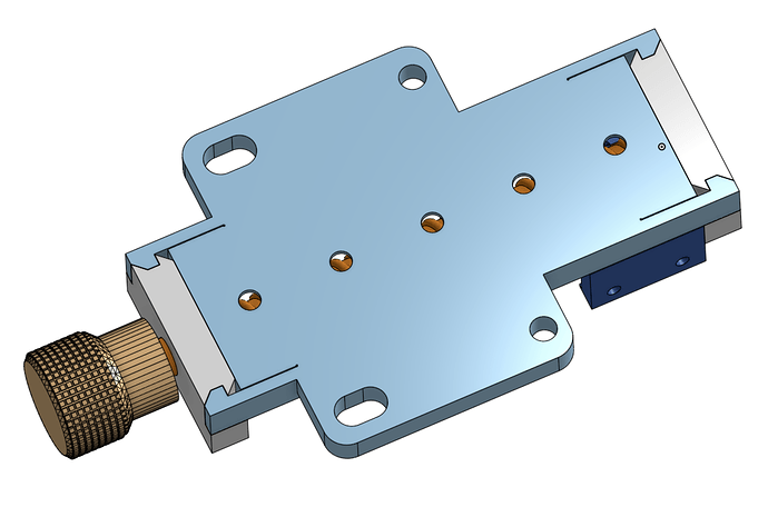
Alright, an adjustment here… and an adjustment there… and I have, with the exception of six M3 screws and four M3 nuts, a “Completely Printed Z-Axis Mechanism” (CPZAM) for cheap laser machines. :face_with_raised_eyebrow:

A bit thinner yet again than its predecessor…

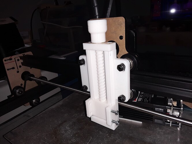
mounted on the Fokoos machine…

with Fokoos laser module and adapter plate…

and Neje A40640 dual diode laser directly mounted (no adapter plate needed)…

Please know that this is not the smoothest operating mechanism there is… but, in this case, it helps keep the laser at a constant height without a locking mechanism. My earlier version(s), with rods and bearings, could actually fall under their own weight at inopportune times. But it is “smooth enough” to allow easy and relatively precise height adjustment for focusing, etc. It has right at 9 complete turns of top to bottom adjustment… a range of 75mm total travel on the slide; i.e. about 8mm per turn of the knob.

An observations about printed sliding surfaces… it helps if the mating surfaces are NOT printed at the same resolution and with layer lines running in the same direction. To test I printed two sliding mechanisms…

the vertically printed set hardly slides at all without considerable force applied , the horizontally printed set slides better but feels a bit “sticky”… but mismatch either set and it is “just right”. Sound familiar? :roll_eyes:

For the “threaded” parts – the leadscrew and carriage – I felt both needed to be printed oriented vertically… to insure their cross-section is as round as possible. In this case, I found that if I printed one at 0.3mm layer height and the other at 0.2mm to “mismatch” the layers… I got smoother operating threads than if both were printed at the same resolution.

Anyway, again… as this Z-lift isn’t for continuous, high-speed operation and heavy loads, this is a case IMO where printed slides and threads make sense. As long as it doesn’t melt or get broken by a “heavy-handed” gorilla… maybe it’ll last as long as the machine it get installed on? Only time will tell… :wink:

– David
7 Likes

For those following along, I’ve published this latest “improved” Completely Printed Z-Axis Mechanism (CPZAM) out on Thingiverse. SIL insists that since it’s held together with M3 screws/nuts that it isn’t “completely printed”… anyone for a Glued-Up Printed Z-Axis Mechanism (GUPZAM)? Or, a Snap-Together Z-Axis Mechanism (STZAM)?

:stuck_out_tongue_winking_eye:

– David
2 Likes

This looks amazing. Thanks for the effort and thanks for sharing. I follow the V1 forum because I built an MPCNC but my start into the CNC world was an Acro Laser so this caught my eye and I had to give it a look. I agree, adjustable Z is essential with a laser to focus properly and adjusting the lens sucked. I eventually broke down and built another version that was WAY more complicated to build than this (but it motorized so in the end more convenient). I would gave gone your route for sure to start.

Awesome.

1 Like

Thanks for the kind words. Z-mechanisms have kinda become my “thing” and about 3 versions back, I did my motorized version… then made it manual… then simplified again by removing all the metal bits, save the six M3 screws/nuts holding this last one together… :stuck_out_tongue_winking_eye:

1 Like

OK, I REALLY like the travel of your motorized one (not to mention the simplicity) and I think that will work great on my Acro laser. Time to print it and see how it works. The one I currently have is only about 13mm travel! I like it.

I suspect you posted that after I had mine printed but I still would not have found it because I was looking for Z axis specific to Acro laser and I would not have found yours on Thingiverse… But now that there is this forum discussion I am sure others with Acro Laser will find your Z axis contributions. Thanks.

1 Like

Maybe you can convince Revell to release a SnapTite ™ version.

2 Likes

I guess I’m too impatient. While waiting for Revell to call… I took the bull by the horns and put “horns” on the… well, you know…

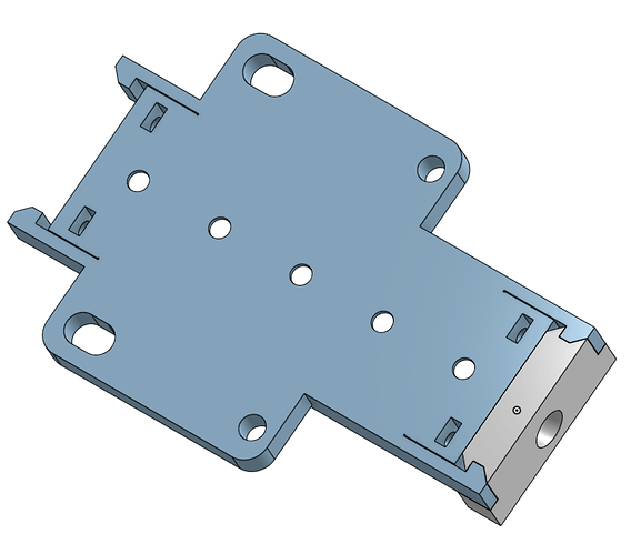
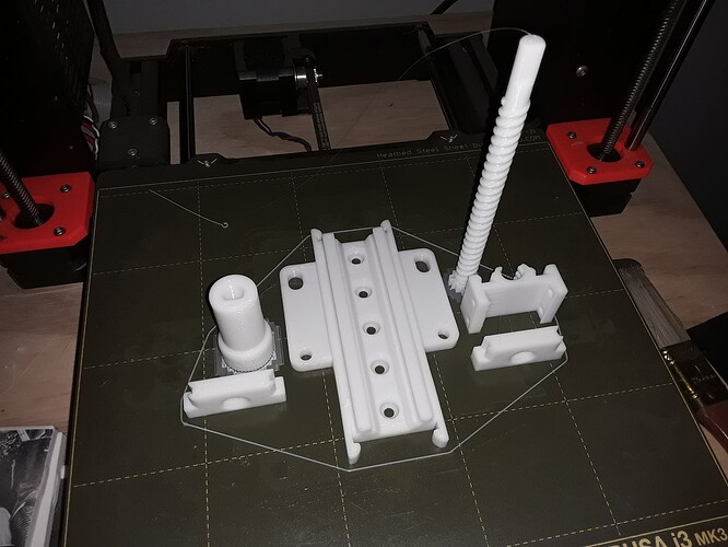
I left some features (holes, nut traps) that weren’t in the way still on the slide-rail body but did remove the counterbore holes from the end-plate so you’ll know I wasn’t “cheating”… :wink:

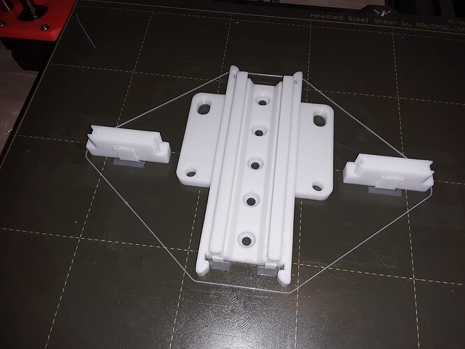
On the print bed, printed at 0.3mm layer height… probably didn’t need support…

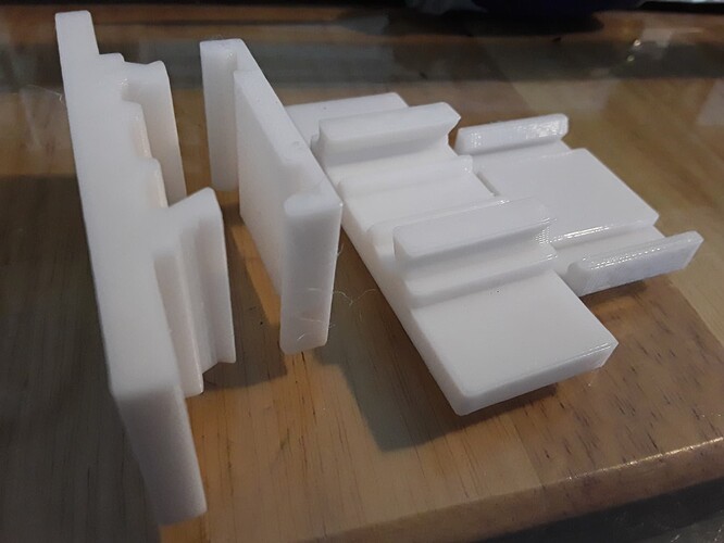
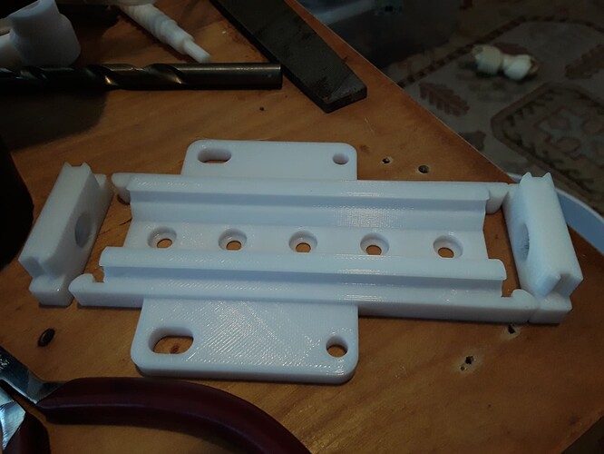
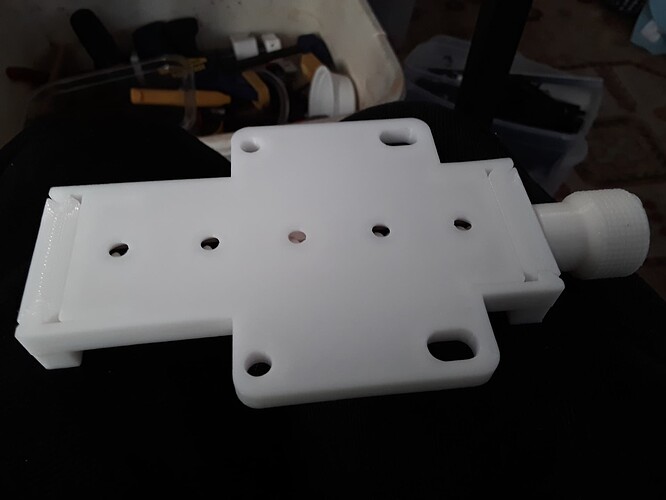
cleaned up a bit… endplates shown upside down to show mating features… can actually be snapped into place or slid apart from bottom

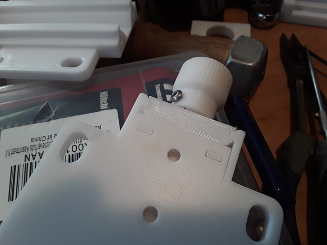
the knob and leadscrew with M3 hardware are just early parts used for test fit… no hardware on later versions…

and, finally, with and without M3 hardware… SnapZAM and NQCPZAM (not-quite-completely-printed Z-axis mechanism) side-by-side…

Surely, Revell will give me a call “shortly”… :wink:

– David
5 Likes

Cleaned up the design… modified internal structure a bit to accommodate central row of mounting holes…

Printed at 0.3mm layer height… then another leadscrew at 0.2mm for smoother operation (can’t have too many leadscrews!)…

the hook slit in the slide-rails body probably aren’t completely free so may need a little coercion (lightly tapping hooks against the endplate mating surface usually forces at least one of them loose…)…

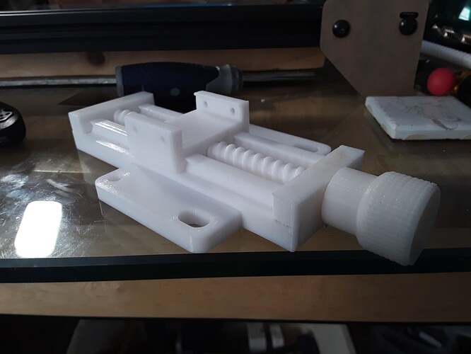
bottom-side with mated surfaces and several mounting options…

“completely printed” vs “almost completely printed”…

CPZSnap? CPZAM? I’ll play with it to make sure it stays intact in use and then probably put it out on TV in a few days…

– David
4 Likes

I keep thinking that I should make one of these… And then you improve it…

1 Like

Oy vey! I was just about to print the last rev when I got home! I wish all development progressed at these speeds. I’ve been thinking about getting into Star Citizen, and that’s been in Alpha for ten years!

Keep it up! I’m going re-fitting my laser rig this spring with your Z.

Now I just need to get my printer to print circles that aren’t all warbly.

1 Like

nice. I was going to add a motorized Z to my laser, but seeing this, I might just opt for a manual one.

1 Like

Good grief! :stuck_out_tongue_winking_eye:

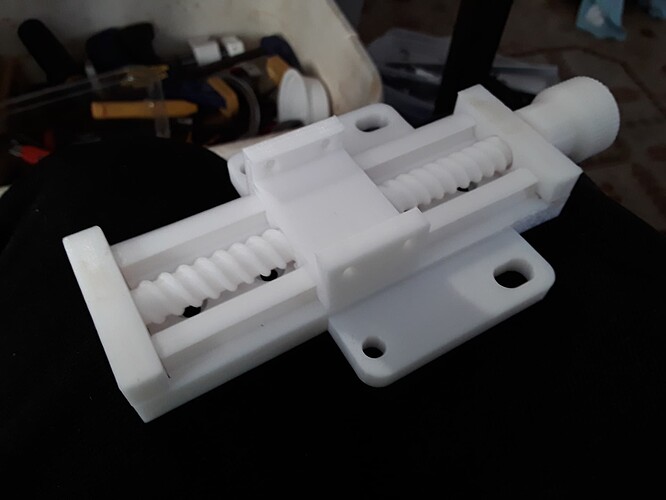
I decided to put the snap-together version out on TV just this morning. I’m still editing and moving things around but already have folks downloading and trying to make stuff from it… and talking about missing files and such. Please know I’m going as fast as I can and will officially announce it here when I think it looks okay.

Wow! Nice “make”, Tim! Thanks for all the interest!
– David
3 Likes

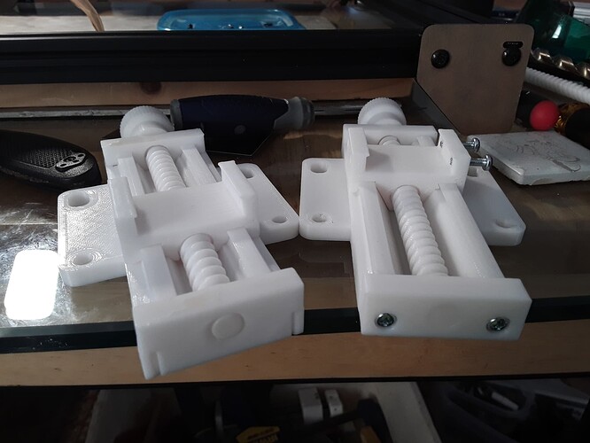
Okay, I think it looks about right now…

I don’t see this changing much anymore, now that it’s attained “completely printed” status… unless, of course, it tends to explode or somesuch. Enjoy!

– David
5 Likes

An observation… after messing about with a couple of laser engravers I have out to play with – Fokoos and Eleksmaker A3 – I’ve found that I actually prefer the “Improved” version (with M3 hardware) of these Z-axis units to the “Snap-together” version (no hardware). Primarily, because the improved unit can be easily and repeatedly taken apart where the snap-together one can’t [easily]. This is necessary when accessing the M4 mounting hardware under the leadscrew (and on the center-line row of mounting holes) during installation on some manchines; i.e. as on my Eleksmaker A3 machine, where it needed to be assembled-in-place during installation. While the snap-together unit was fun to design/develop, for “completeness” sake, it’s just not as flexible/adaptable to as many machines. Oh well… :crazy_face:

2 Likes