Hello V1 Engineering Community!
I’m excited to share some major upgrades and improvements I’ve made to my LowRider V3 over the past few weeks. After finishing the initial build, I quickly identified areas where I could boost performance, stability, and accuracy. Below is a detailed rundown of the modifications I’ve made, and I’ve included pictures as well to showcase the changes!
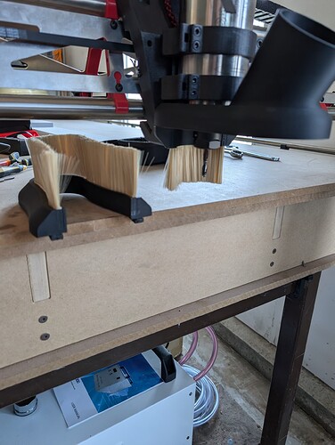
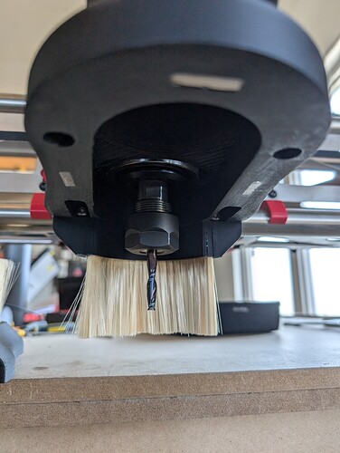
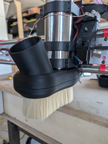
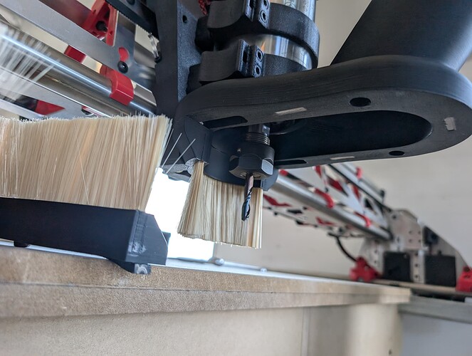
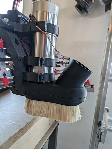
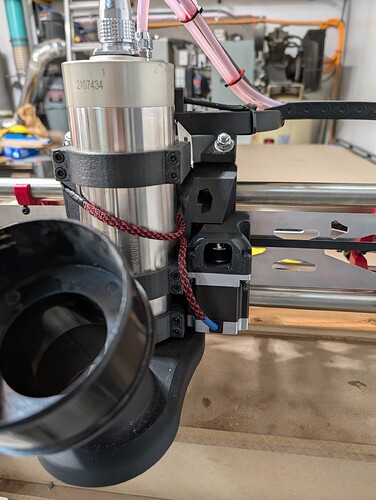
1. Custom Dust Shoe for 2.2kW Spindle
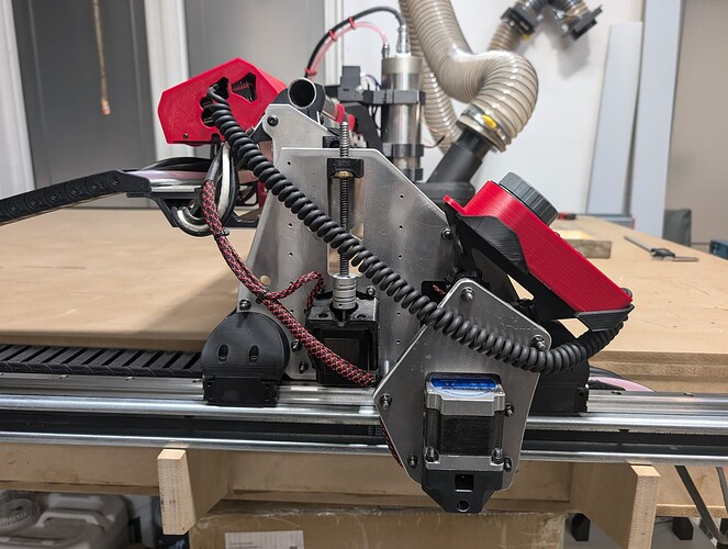
First up, I completed my custom dust shoe design for my 2.2 kW spindle, and it’s working great! I’m really pleased with how it turned out. The dust shoe captures debris efficiently, keeping the work area clean while cutting. You can check out the photos I posted to see the design in action.
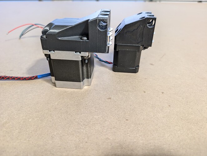
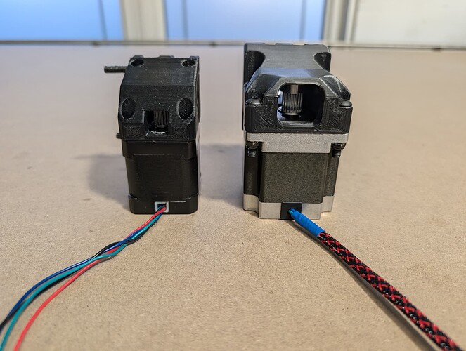
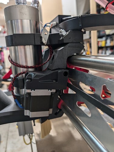
2. X-Axis Upgrade: NEMA 23 Motor Installation
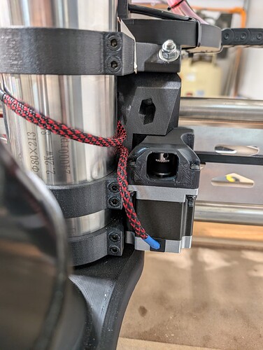
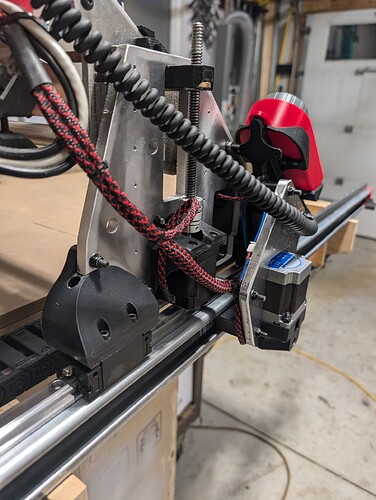
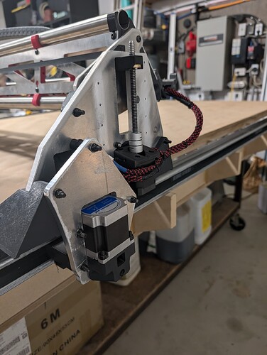
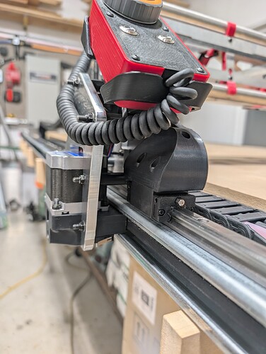
After assembling the LowRider V3, I noticed weak performance on the X-axis, which isn’t surprising given that it’s only driven by a single motor. To solve this, I upgraded the X-axis motor to a NEMA 23 motor (23HM22-2804S). This motor can handle up to 2.8 amps peak power and delivers 1.26 Nm of torque, which is a significant improvement over the original NEMA 17 motor.
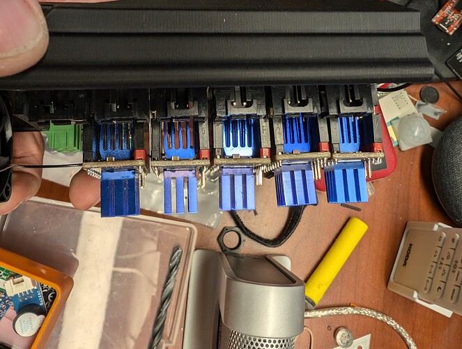
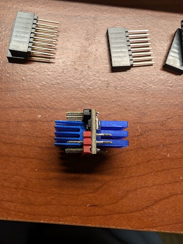
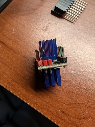
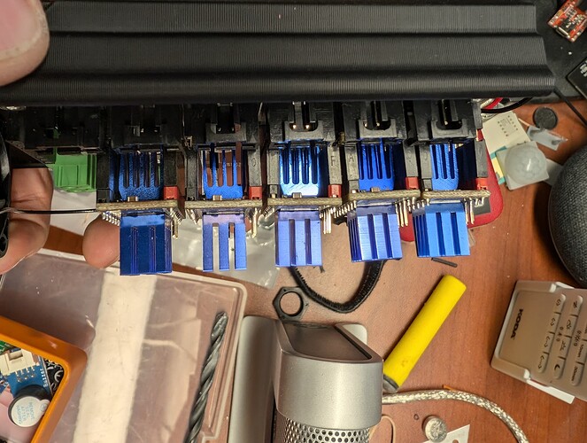
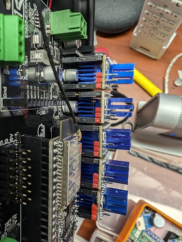
However, I was limited by my TMC2209 drivers on the Jackpot controller. To ensure the NEMA 23 would perform at its peak without overheating the drivers, I came up with a cooling solution by attaching heatsinks to both the top and bottom of the driver, doubling the heat dissipation capacity. I extended the driver legs to fit the modified setup, and after extensive testing, I was able to deliver a steady 1.77 amps to the motor without any overheating.
I also designed a new X-axis motor mount to accommodate the NEMA 23, which resulted in only 10mm loss of travel on the X-axis—something I’m happy to accept for the performance gains.
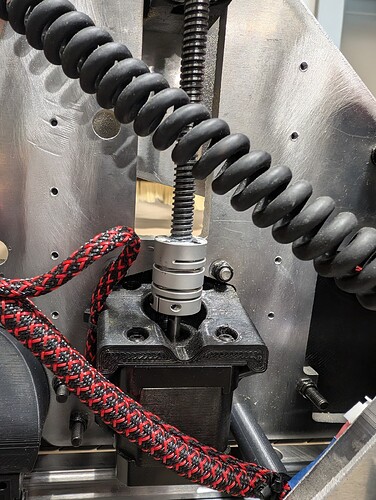
3. Z-Axis Improvement: More Rigid Couplers
During testing, I noticed inconsistencies with the Z-axis depth setting. The flexible couplers were causing too much “float,” resulting in cuts that were either too deep into the spoil board or didn’t cut all the way through.
To address this, I replaced the flexible couplers with more rigid ones, which improved the accuracy of the Z-axis. While a full redesign of the Z-axis would be needed to eliminate the issue completely, the new couplers have significantly improved performance in terms of depth accuracy.
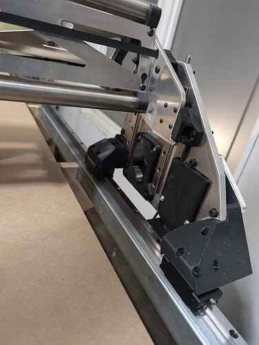
4. Y-Axis Upgrade: Linear Rails and NEMA 23 Motors
I encountered issues with the Y-axis when cutting 3/4" melamine at high speeds. The Y-axis was jumping on the Unistrut, causing accuracy problems. To fix this, I upgraded the Y-axis by installing HG15 linear rails, which I found on sale at Vevor. Aligning these linear rails was a significant challenge, but after carefully working through it, I was able to bolt down the Y-axis, eliminating the jumping issue.
While working on the Y-axis, I also decided to upgrade to NEMA 23 motors for the Y-axis drive to match the power of the X-axis upgrade. These changes made a massive difference in the stability and precision of the machine.
5. Fluid Pendant Addition
I also added a fluid pendant, which has been a fantastic addition for ease of control. This makes jogging and adjusting the machine much smoother and more intuitive.
6. Milling Aluminum Y-Axis Motor Mounts
Before implementing the upgrades, I used my LowRider to mill new Y-axis motor mounts from 10mm aluminum, and I was impressed with the precision and quality of the final parts. The rigid aluminum mounts have further increased the stability of the Y-axis.
7. Test Results: Pushing the Machine to Its Limits
After completing the upgrades, I ran several test cuts. One of the most significant tests was clearing a 100mm x 100mm pocket, going 12mm deep in one pass on a 2"x6" piece of wood, using a 1/4" 2-flute upcut bit. The machine handled the cut at an impressive 160 inches per minute (IPM) feed rate, and I’m very happy with the results.
Reflections on the Challenges
I wouldn’t call this build easy by any means, and aligning the HG15 linear rails was one of the more challenging aspects of the upgrade process. However, the result has been well worth it. The machine is more powerful, stable, and precise than ever before, and I’m excited to keep pushing its limits.
Next Steps: Vigorous Testing
I’m looking forward to conducting more vigorous testing to see just how far I can push this machine. If anyone in the community is interested in helping me test this new design and provide feedback, please reach out! I’d love to collaborate with others and get insights into how we can further refine and optimize these upgrades.
Thanks again for all the support and advice from this amazing community—I couldn’t have gotten this far without it!
Looking forward to hearing your thoughts!
Cheers,
Walter
Pictures will be added soon…
