I wasn’t going to develop this further until my LR3 was finished, but watching Doug’s KINEMATIC Tool-less holder has got my juices flowing a bit, so tomorrow I’ll probably print it and load test.
I started sketching this connector quite some time ago, became interested in MagSwitches and thought for light loads there had to be a simpler way without mucking around with bits of steel rod. I tried something similar on my original vac connector but couldn’t get it small enough, but of course my workshop duct connectors work very well at 100 and 150 diameter.
My design considerations were:
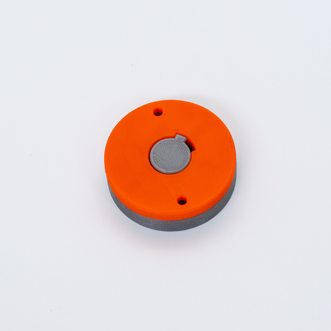
- Had to be as small as possible (this is 15mm x 50mm diameter)
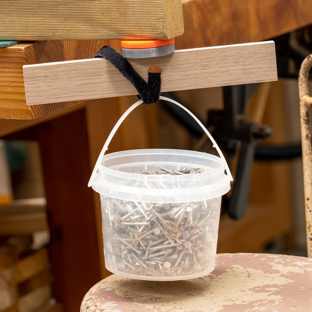
- Easy to connect and disconnect (by using magnets in alternating poles, a 1/6 turn is all it will take to repel)
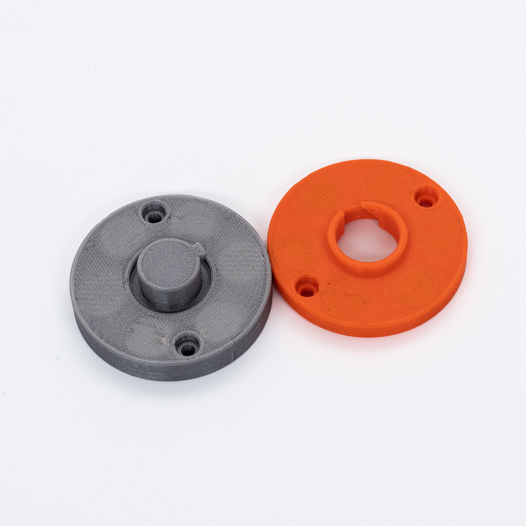
- Had to resist shear (cross) forces (hence the male and female core.
- Must be able to consistently locate in the same position (Doug’s Kinematic coupler is absolutely the winner here) - I think the magnets will work too, and that’s why the little projecting bayonet.
- Print without supports
- should be a stand alone print able to be bolted onto a flat base, or incorporated into a fitting if the geometry will allow magnet insertion.
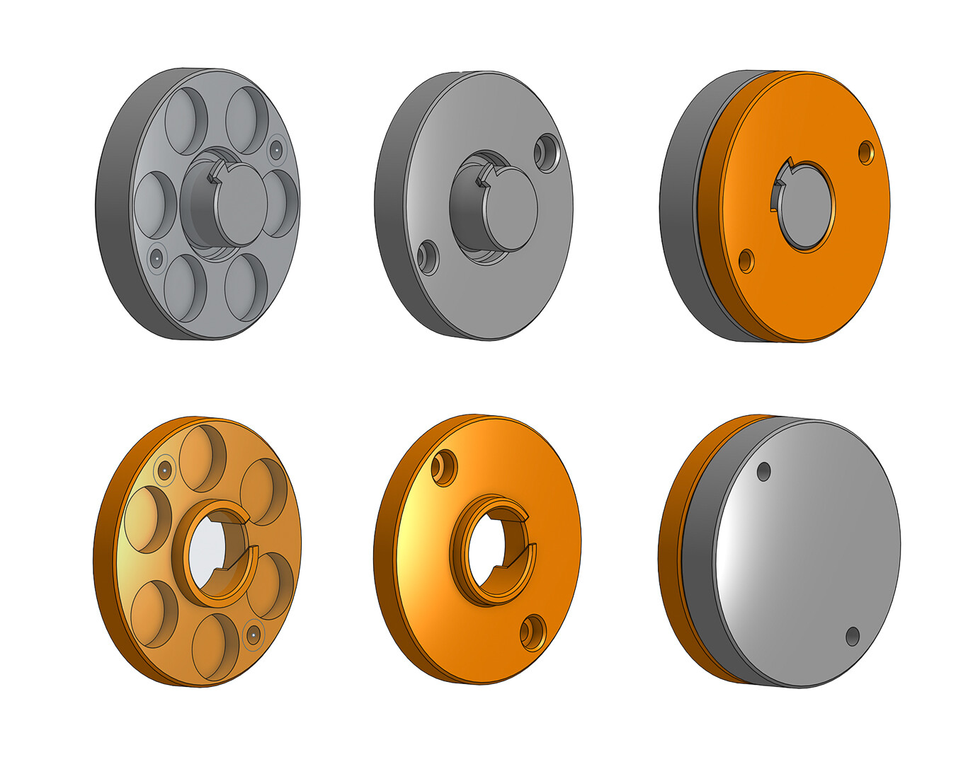
I think I’m there, but until I test it with real loads we can’t be sure. The image below should explain the workings - the magnets will be encapsulated in the print with a 0.4mm skin over them I’ll probably make them 3 layers @1.2 but will test 2 @ 0.2 as well.
There’s enough depth in the “GREY” part to double the number of magnets in it (I’m proposing 12mm x 3mm), and adding 1.5 mm to the overall dimension will double the number in the “ORANGE” part. So there’s a little wiggle room if it doesn’t turn out strong enough.
Until tomorrow evening this is all theory of course, so hold your collective breaths till then!
Top be clear, the left hand illustrations below are just to indicate the magnet positions.