I discovered the robot acts drunk when the battery is low. I didn’t plug it in overnight and when I told it to go somewhere in the morning it went in the general direction and then plowed into a box.
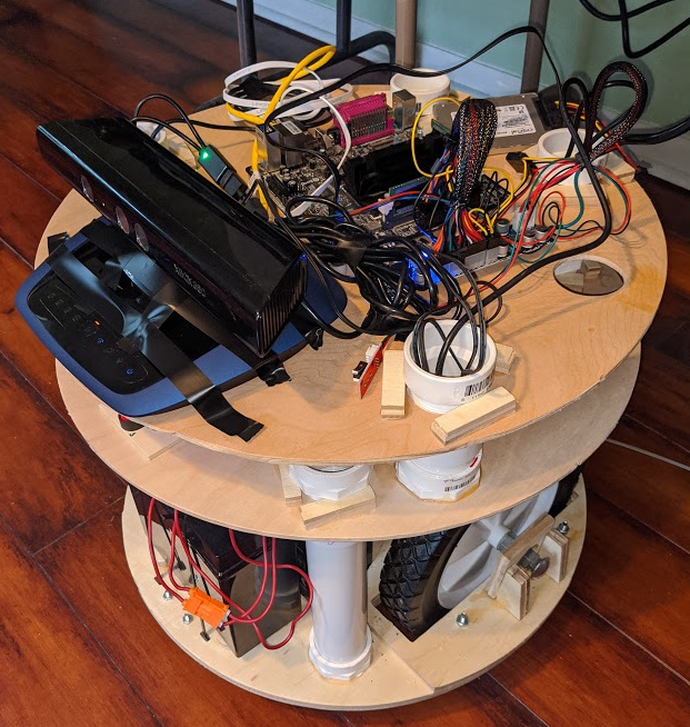
Here’s a recent photo (forgive the electrical tape… its temporary).
The laser scanner is on the second level with all the power converters and terminal strips (you can’t see it). I want to redo the support pipes there to minimize their cross-section and reduce the amount of the laserscan that’s lost. I like the laser scanner being there since its relatively protected from 8-year old humans and 1-year old dogs.
I repurposed an old dd-wrt router and configured in client mode to function as a local ethernet switch/wifi bridge. Now, the mapper, computer, and soon-to-be-installed jetson nano will all talk via ethernet.
I’m working on getting my lowrider back working (finally getting around to putting the new belt holders on) so I can cut a new platform to relocate the kinect and install the jetson and cameras.
Honestly, I don’t know which would be better. The XBox One version has a wider field of view which is better, but not sure about how the other specs would play in. I worry that too much data will bog down the computer.
One thing that I noticed is that with the turtlebot (a commercial product that uses a kinect) is that the connect is mounted in the rear, facing forward. I wonder if this is done because the kinect has a minimum distance spec. I have mine at the very front and when I do the new platform for it, I’ll look to see if mounting it in the rear improves its performance.
But, as for the XBox One kinect… hold on to it because I might have a use for it down the road when I start looking at trying to do things with a 6dof manipulator. Having a depth camera tracking the arm would be handy…
I’ve further ‘calibrated’ the position of the kinect and it lines up with the laser scanner output well. I was off by a few centimeters before and adjusting the position really helped the robot to manage to navigate through a doorway. Being 20 inches in diameter, it’s not easy for a computer with imperfect senses to navigate through a 29-inch opening. That’s 4.5 inches on either side and the senor data is noisy. It’s funny what we take for granted.
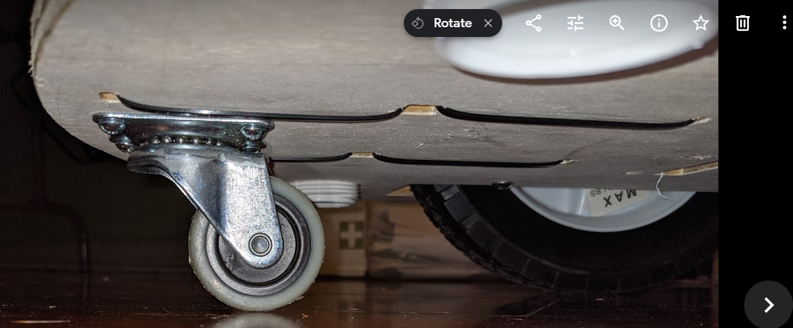
However, I now have a new problem and need ideas. I have wood floors with a transition strip along the doorway. When the robot is trying to navigate through the doorway, it does so slowly because of the relatively narrow path it has to navigate through. The front caster has a small diameter and bumps up against the front of the transition strip and it stops the robot from moving forward (it’s not a smooth transition). If it had speed, it would just run up the bump but because its slowed down so much (and even stops) it’s a problem.
The caster is small (1.5-inch diameter) and directly under the batteries (the zip ties are arranged to secure the two batteries) so there’s a lot of weight forward. I really don’t have a ready solution to this problem that doesn’t involve putting in a larger caster by cutting off the nose of the robot and rebuilding it… but I’m not sure that would solve the issue.
An idea came to me while shaving (always when they do… I should start shaving 3-4 times a day) that I should drive the robot in the other direction so the big wheels are the front and the caster is in the rear. That way, the robot will already be in through the doorway and moving prior to the small caster running up against the transition strip. AND in doing so, its likely that the caster will strike the transition strip either straight on or at a slight angle, which should also make it easier to get over it. To make this work, I think all I need to do is to turn around the laser scanner (though I might just be able to just transform it) and the kinect (which can’t be transformed since its not omnidirectional) and change the pin assignments on the motor controller.
Switching things around worked out well. Robot can move across the transition strips now.
I had been trying to get the kinect working with a voxel obstruction layer and I think it was just taxing the computer too much. It just couldn’t successfully and repeatedly navigate through the door way. I switched to depthimage_to_laserscan and created a local costmap using the kinect laser scan plus the mapper’s laser scan and a global costmap using the static map plus the mapper’s laser scan. So far so good. I also took out two of the support posts holding up the top layer. it’s a little flimsy but is holding… now the mapper’s laser scanner has a good view when it passes through the doorway.
I’m now playing with my new 3D printer trying to get it to work so I can make some parts for the robot. I think I need to build an enclosure for it since the parts pop-off during the print. The bottom edge starts to warp away from the build plate and eventually pops off entirely… I can hear the popping sounds as parts of it start to pop away. I’ve got an AC vent in the room I closed off, but there’s still lots of cold air blowing in.
If I were to 3d print new bearing mounts for the wheels (replaced the 3/4-inch plywood assemblies) would PLA be too weak? There’s a lot of weight resting on the bearing mounts. I hear abs is much stronger, but gives off nasty fumes when being printed… and it’s hard to print. PTEG? I only have experience (minimal at that) with printing with PLA.
I relocated (at least temporarily) the kinect to the very bottom to give it a better view of obstacles. I had it on top but when a short obstacle (below height of the 360-degree laser scanner) passed out of it’s view (below the kinect’s vertical field of view), it disappeared from costmap and the robot ran into it. So I dropped it down to the first level and that solved that problem… the robot would turn to avoid the obstacle. But then when the obstacle passed out of the camera’s horizontal field of view, it disappeared from the costmap and the robot turned back into the obstacle.
I figured out what was happening… the local costmap uses the Kinect and the laser scanner. Both were set to mark obstacles and clear obstacles. Because the short obstacle was below the laser scanners level, the laser scanner was clearing it from the costmap as soon as the Kinect stopped marking it. So I changed clearing to false for the laser scanner for the local costmap and kept it true for the global costmap and it’s working much better. I might relocate the Kinect back to where it was to see if it performs just as well.
I have watched enough robot demos where the robot is going to be operating in a “new” environment, and the story is that it just works everywhere. But you see the teams there before the demo, bringing their own obstacles (why would you bring a barrel 1500 miles with you ), trimming the local fauna, changing the routes. You’re getting a sneak peak at the real challenges of robotics. These are the “corner cases” that are still very much a big problem.
When you turn off the clear obstacles, the next issue is that if your wheels slip, the costmap will smear, and it won’t get cleared (which is fine). But that will lead to other corner cases. Maybe the SLAM will save you.
This is why we were happy to pay $70k for the first velodyne hdl. 64 scan lines spinning at 15Hz, producing 1.3M points/second and at least 30-50m range. It gave us so much more information than the stereo cameras and single line SICK lidars we were using before. Even though we were still mapping and planning in 2D.
That makes sense. I have folding tables in my lab and the mapper sees the vertical inner posts but not the feet. The kinect notices those, but when its close, its out of the field of view.
But it seems that the feet don’t clear from the local costmap now that I stopped the mapper from clearing the local costmap as long as the kinect picks them up.
I’m certainly not trying to make a robot that just works everywhere… just my home… so I can do hacks to make it work in that environment. I’m thinking of maybe trying an array of low-cost sonar or lidar sensors around the base to pickup smaller items that are out of the kinects field of view. I got a shipment of PLA filament this weekend and used the box as an obstacle. The depthimage_to_laserscan picked the box up when it was vertical but when layed flat on the floor, I think it just assumed it was part of the floor and ignored it. Maybe sonars positioned along the base might be able to pick it up.
I discovered that the reason the kinect wasn’t seeing the small box on the floor was that the small box on the floor was just below the centerline of the kinect. Apparently, the default for depthimage_to_laserscan is to scan just one horizontal row at the centerline of the image to come up with the laserscan. So anything below that (or above it) will be ignored. In order to increase the vertical range, you have to change “scan_height” parameter. Once I set the scan_height to be equal to the height of the depthimage, it found the box. But my CPU usage went through the roof and there’s no parameters in the code that you can do to reduce it. I find it really odd that with a 480 row image, you can’t just tell it to scan every 10th row… you have to scan every row in order to reach the bottom row.
I looked at the source code and think it would be easy to modify to skip rows. I found the line in the code that processes the scan lines:
for(int v = offset; v < offset+scan_height_; ++v, depth_row += row_step){
The plan is to, at least at first, add a simple hardcoded value to multiply v and the row_step:
for(int v = offset; v < offset+scan_height_; v = v + 10, depth_row += row_step*10){
If that works, I might bother with making it a param so I can adjust it without rebuilding… and maybe a PR… I’m really surprised this hasn’t already been done.
Now to figure out how to modify and rebuild it (I think it was installed via apt-get).
You will make a “workspace” with the source code (do you already have one for the launch files and parameters?). You can just download that package source there and it will overlay the /opt/ros/ one. I would use catkin-tools, not catkin_make to build it if you can. It is much nicer. I would also put in a ROS_INFO log statement so you can be sure it is running your version of the code.

 ), trimming the local fauna, changing the routes. You’re getting a sneak peak at the real challenges of robotics. These are the “corner cases” that are still very much a big problem.