When I send a job using machine bed for the Z axis origin in Estlcam V11 it plows into the material and dives to the spoil board’s surface and begins the cut at and into the spoil board.
Sounds like “Working as Intended”, or “GIGO”, or “PEBCAK”, or whatever euphemism you want to choose. But that’s only because from the very minimal information you’ve given, it sounds like it’s doing exactly what you’re telling it to do. You’ve zeroed the work surface, and told it to start cutting. How is it supposed to know that you zeroed it to the spoil board, and not the top of your stock? We would need to see at least the start of your gcode (up until it actually gets into the cutting moves) to properly diagnose what’s going on.
If you’re going to zero to your spoil board, you need to make sure you let it know there’s an offset to the workpiece (your desired stock thickness).
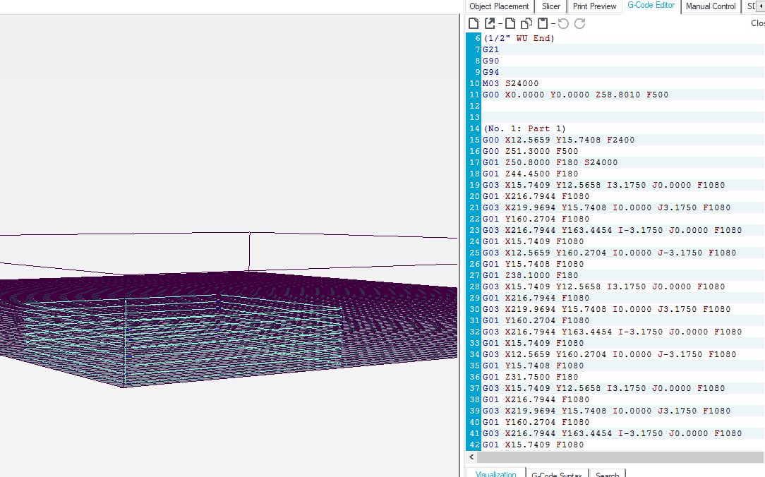
If you’ll post the first couple dozen lines of g-code, I’m sure the gurus will be along to help out. I’m good at pointing out likely problem areas, not so good at providing actual solutions…
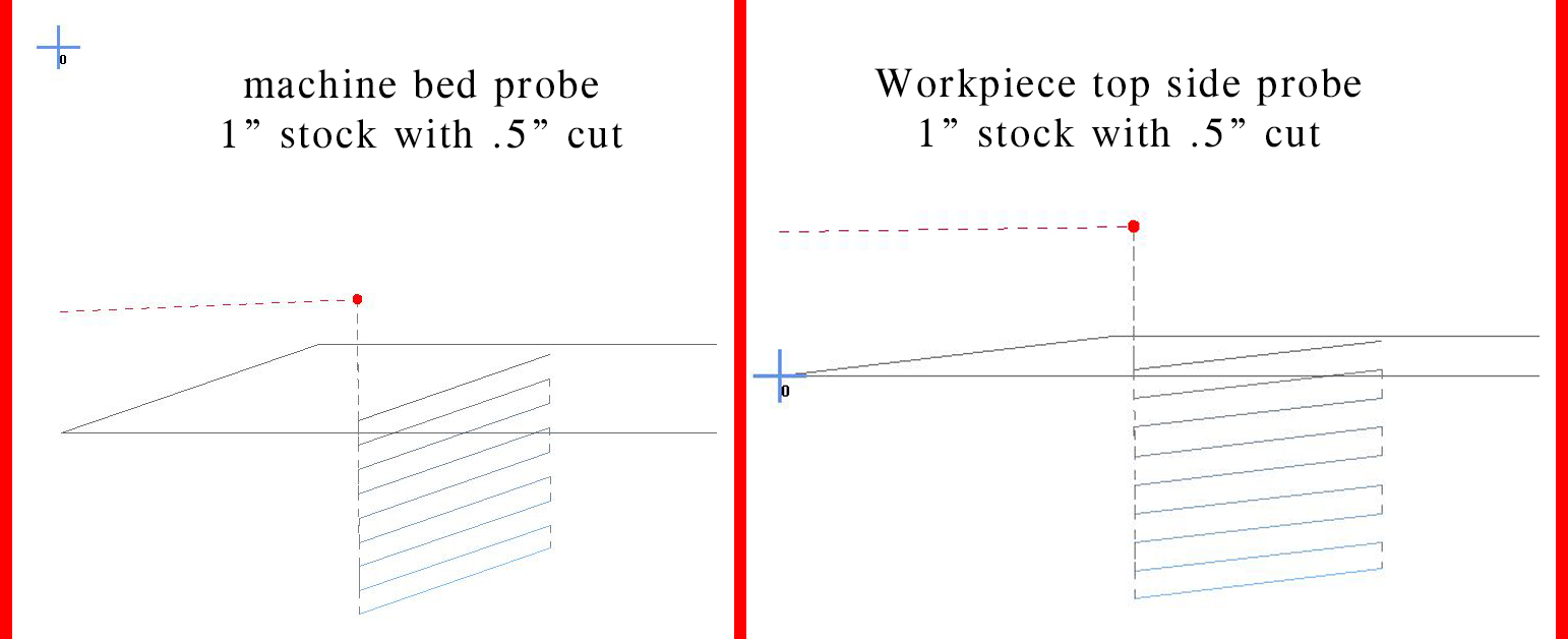
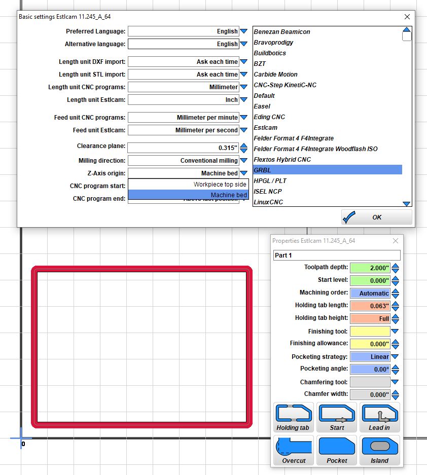
You can set the spoilboard as the Z=0 but Estlcam’s default behaviour is to treat Z=0 as.top to the material.
To use Z=0 as spoilboard, you have to set the “starting depth” for each cut, and make sure you set the travel height to be an actual safe height above your material
If you want it to cut 2" down and stop at the spoilboard, set the “start depth” to -2"
The start depth is where Estlcam will make the start of the cut. Typically this is used for if you want to make a cut inside a pocket. For example, say I want to have a screw hole at the bottom of a cupped part, I would pocket out the cup, say 20mm into 25mm thick stock, then cut a 5mm hole with a start depth of 20mm. Here it avoids wasting time by cutting air.
For what you have set up, you want it to start 2" above the Z=0 plane, so set the start depth to -2" and the cut depth to 2" and it will end the cut at the zero plane. Note that you really.do need to make sure that your clearance plane is greater than 2" or else the tool will cut through the side as ot returns to X=0, Y=0.
Hmmm. That is kind of what the spoil board is for… though you dont want to cut through the spoil board, certainly.
Most times when I am cutting things out, (working in mm) I set my cut depth to be .5mm more than the expected thickness of my stock, to be sure that I get it to cut through. Sometimes a bit more for larger pieces even, since I know my table isn’t as flat as it would ideally be.
indeed, but may be a regular table is used for now. I would add some thin piece of mdf, like 4mm thick, and put that between the spoilboard and your workpiece if you want to keep your spoilboard intact. That will be a lot easier than setting Z=0=spoilboard
Well, I set up my jobs for Z=0 at the top of my work, so I didn’t know that. I thought the 2.5D milling page had it set up this way, though I did my LCD case the same as I normally would.