I built the dual endstop lowrider v3. It seems to work as it should however, I am having trouble squaring the machine. It seems m666 command doesn’t work on the y axis. It gives me an echo: endstops hit y:0.0 message. If I apply an offset to the z axis it works fine. Not sure where to start. I am hoping someone had run into this problem in the past. Thanks!
Please share some details of what main board you are using, what Gcode scripts you’re using, or what you are handtyping as far as Gcodes in the terminal. Also, maybe take some pictures and post them. We will do our best to help.
M666 Gcode works for Marlin firmware, on main boards that are using Marlin. Below is a video showing that an action.
LowRider 3 CNC - check for square & mark grid for registration
For the Jackpot main board, which does not use Marlin, but rather FluidNC, then you need to use a different approach, by editing pulloff in the config. The videos below illustrate that other approach in action.
LowRider v3 CNC - Tramming & Squaring with Jackpot controller
LowRider v3 CNC - Squaring table with Jackpot controller! (WIDESCREEN VIDEO FOR PC)
LowRider v3 CNC - Squaring table with Jackpot controller! (VERTICAL VIDEO FOR PHONE)
I have the SKR 1.3Turbo. Using tft35 and manually typing m666 into the terminal function. M666 works as it should on the z axis. I can watch one side or the other move away from the end stop and the offset is shown in m503. For y axis it shows in m503 but the axis doesn’t physically move. I’m thinking I’m going to shim the belt holder where the y end stop touches to mechanically change it. Just thought it was weird that it would work on one axis and not the other. Thanks for the links and reply’s.
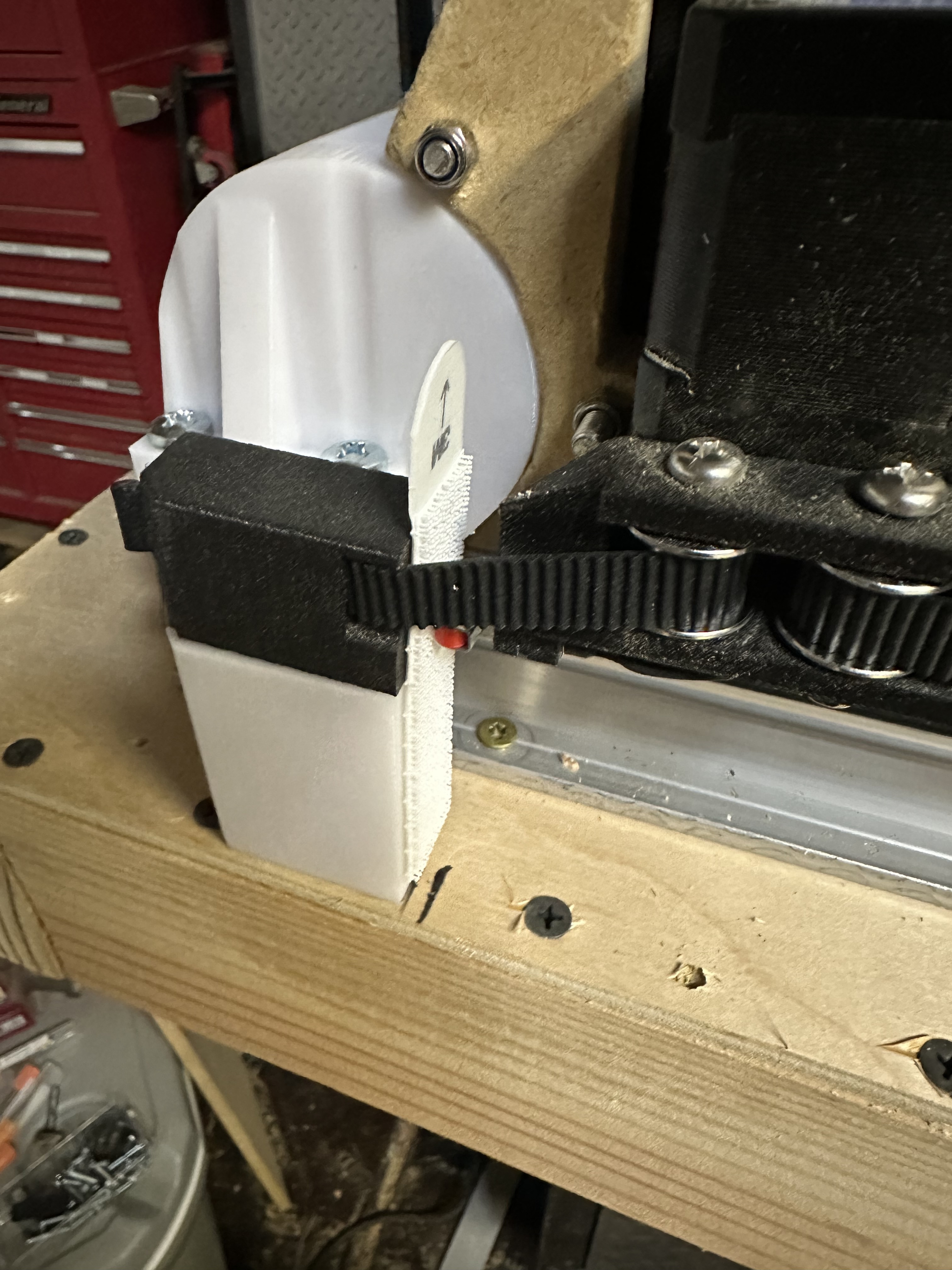
It would be a good idea to get that angle out of the belt, and have the belt be as straight as possible on both sides of the Y pulley.
The reason is that there is some error introduced by that angle as the machine travels on the axis. The actual distance travelled is a factor of the cosine of the angle of the belts on both sides of that pulley. The closer you can have that to an ideal “1” the better. You can’t just adjust steps/mm with that, because the angle changes with the distance from the belt anchor points, so the steps/mm is different right next to the home than it would be in the middle of the axis.
Now if you never need better accuracy that this gets you, it might not be a big deal, but I know that I use a CNC machine to get better than tape measure and sharpie precision measures.


")
")