Hello, I am completely new to CNC I build lowriderv4 with Jackpot from here and by the guide. But my Z axis is not behaving like I was expecting.
When I home, X and Y are both fine, but when I try to home Z axis it goes down so not the way end stops are, is this right? When I click on Fluid on Z to go up, it goes Up, so it seems the wiring is right.
And can someone please explain me a bit more, how to use touch plate, I have original V1 and I was expecting when it touches it should not go further down, but that is not happening.
Despite above I was able to cut my sturt plates with it, but without homing Z I am not able to check if it is horizontally to the table. Moreover every time I shut it down left side (min side) goes down. So far I screw down the max side as well to get it as level as possible, but this seems to me not to be permanent solution.
P.S. I am not native English speaker, so please dont hate me for my bad english
That usually means you have the steppers plugged in “flipped” the wrong way round.
Homing Z on LR4 goes up to max travel.
This also means your Z is moving the wrong way. Z should home up to max travel, then the probe should come down and stop when it hits the touch plate.
This is actually a good sign and is expected. It means that side is properly assembled and the lead screw is well lubricated. The LR4 uses the stepper torque to hold itself up. If you disable the stepper, then a freely running axis can drop. Most users make blocks to set the machine on before powering down.
Y and Z axis self-square, so there is no need for you to manually adjust it after you have finished all the build/setup properly. That you are able to do all this manually and cut strut plates before the machine is fully set up is a good sign. It means you have good fundamental understanding of CNC.
Your English is great!
The community here will help you get your machine all sorted out and running.
Once again, welcome to the community!
Ok, I will try to flipp the connectors.
But how is possible that fluidNC is going up when I click up and programs drills and cuts as well the correct way?
Welcome Michal and congratulations on building and successfully using your LR4 to cut the strut plates.
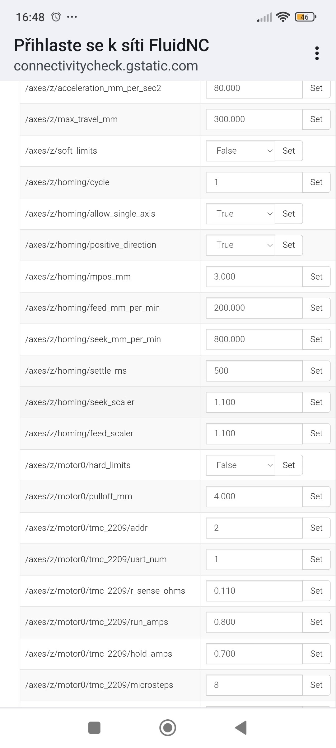
In your config does Z axis Homing show: positive_direction: true?
Well I flipped the cables and it is much worse I guess. Now when I try to home Z it goes up, but it is going by steps like 5mm or something like that. But when it hits the end stop it not stopping. And in fluidNC when I try to go up its going down…
We should sort out your endstop behavior as a first step.
In the FluidNC terminal, type this:
$limits
For each limit switch on your machine, manually press it and then note what happens in the FluidNC report, and also what the LEDs on your jackpot show for status as you do this.
A picture of your board, as wired in your machine, may also be helpful.
This acts like the machine may already belive the endstops are triggered.
Well looks like I am getting constant reply from z, to my understanding, what hitting other endstop do.
So it seems my min z endstop is constantly triggered
Ok, for now I found the issue, there is 1 ripped wire on end stop which is triggering the endstop constantly. Seems I ripped it of during final wiring. I need to partly dismantle the machine. So will see tommorow, I dont have tine to do it now, since have no idea how long its gonna take.
Ok, so here is the progress. As Nathan said, wiring was correct at beginning so I had to flipped it back. After the fixing the low z stop it was homing down… now its homing up and stops at ends stops, so homing on Z axis is fixed and its working as expected. Thanks all for sorting this out.
Just one more question about the touch plate, can please someone explain me step by step how to use it? I have read this section in LR4 build a lot of times, but I dont get it.
Or moreover is that needed? I am planning to flatten the surface of my table with surfacing bit, so it should be as flat as it gets… now I was just moving down the Z axis and when it touched the workpiece I reset the Z to 0 and started from there. Will touch plate help me with that? Or it will help me with removing less material when flattening?
You can manually set z0 for every cut. Lots of people do. The touch plate just simplifies the process. Instead of lowering the tool manually and eyeballing when it touches and then setting z0, you just put down the plate and hit probe. The machine lowers itself until it touches, retracts. And then subtracts the thickness of the plate from the registered touch and sets your z0 automatically.
You want to know how thick your plate is and enter that into the configuration so it accounts for the right thing. Default is 1mm if i recall correctly, but the one i use is 15mm thick.
Yes, @Nathan_Doty called that correctly. The motion was correct, the key was the Z endstop being always triggered was causing the back-off motion, which goes in the opposite direction.
Yes, and aside this you again should check the probing behavior before trying to use it.
One side of the touch plate circuit goes to a clip you place on your router/bit, the other goes to your touch plate. Some routers have at least some continuity to ground through the router itself, so if you have one of those you may need to flip the wiring on your controller to prevent false triggers.
In use, you connect the clip to the router, set the touch plate on your work piece and then send G code to do the probing. Your G code accounts for the thickness of your touch plate, so then your machine establishes Z0 at the top of your work piece.
After that, you can stow your touch plate and start your job.
Have you leveled or trammed the gantry?
You can probe min and max adjust stops before any surfacing.I probe at least 3 times each end average.good video https://www.youtube.com/watch?v=NkXW_XVOLD4&t=41s