Well the original test was simply “does this make the beam stiffer?”
This last one is a good indicator that the machine is much better with strut plates than without, and that the aluminum ones are probably not MUCH better. That’s a pretty good data point.
I was thinking about angle measurements. I have a phone app that lets me use the phone as a level. It has a resolution of about 0.2° which might or might not catch a ~0.5mm deflection, making it debateable if that is twist or bend being measured. It may well be a combination of both, in fact probably is.
This all reminds me that I need to take another stab at making my aluminium XZ plates again, too.
So the goal of the plates are to have the flat, strong edge in line with the load. Meaning, the material should not matter as long as it does not buckle. Seems like we finally got there. The only other solid test now is lock the steppers and measure each part separately to see how the error is stacking up and where it is coming from.
If it is moving 0.5mm, is that 0.1from the mount, 0.1 from the core o.1 from the beam, and 0.1 from the xz connection, or 0.4 from the core alone.
I am stoked it is no different from metal to wood, I am just not really super happy with how much it is moving before the rest of the rest of the system gets brought in. I can’t wait to check a 4’beam versus a 2’ beam.
Pulling the direction you did adds a lot of core into the equation, pulling the other direction should take a lot of core out. If the number doesn’t change, the core is not moving. Easier with an indicator since you can just move it around and see tiny changes.
If I move the core completely at one side, and twist by hand the gantry in the middle, the core twist too…
I’m trying to look closer the YZ area, and seems that the twist is somewhere there. Two points seems to twist: the linear rails and the connection between YZ and Front wheel.
Yes, I know, but the twist starting from the middle must be reduced to the side, this should show deformation of the side structure, it’s a inaccurate test, I know
It is just super easy to apply something crazy like 40lbs of force if you aren’t careful.
So just just be mindful of how hard you are moving things to see other things moving or you could be chasing the wrong moving things. If that makes sense
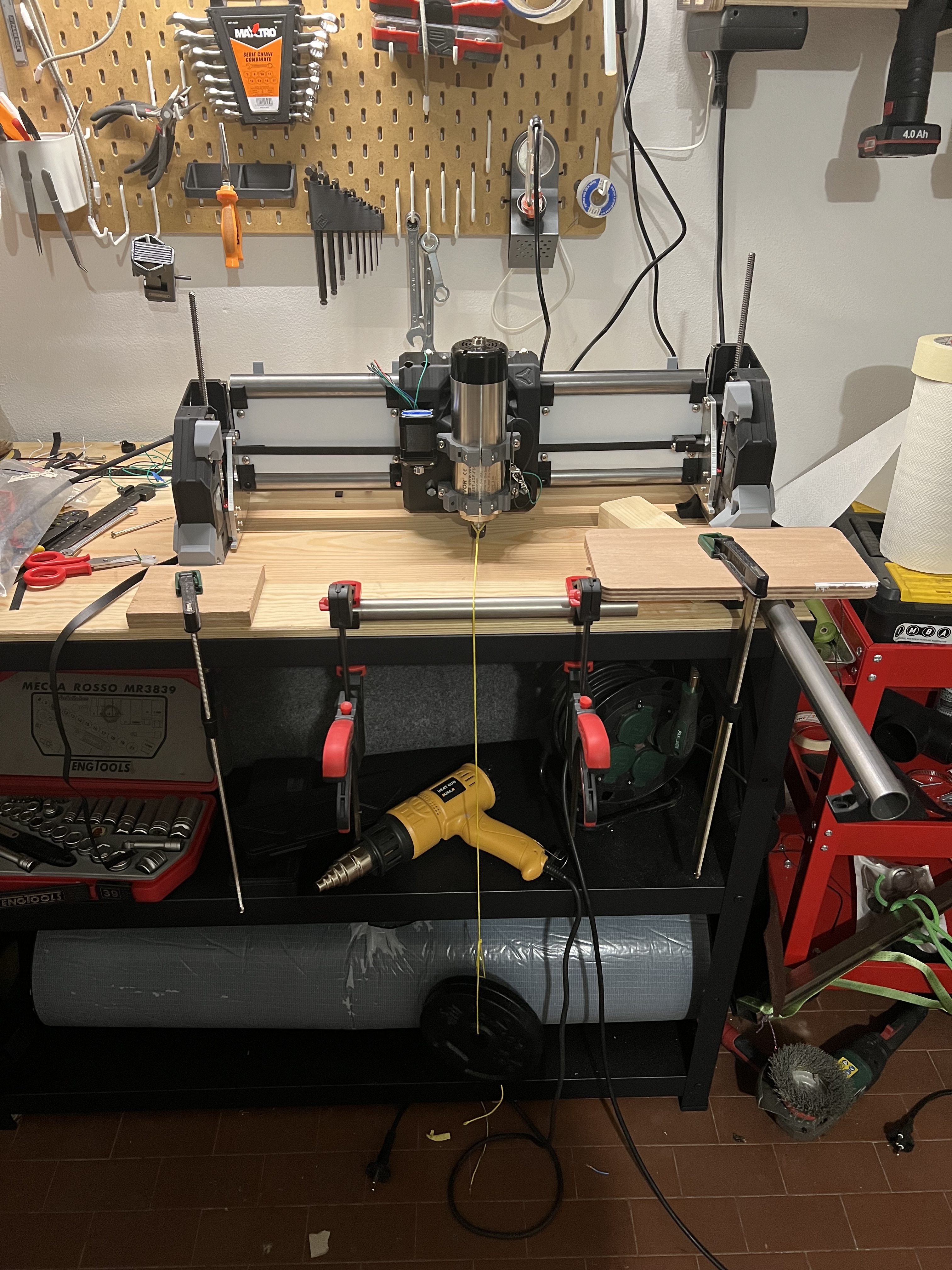
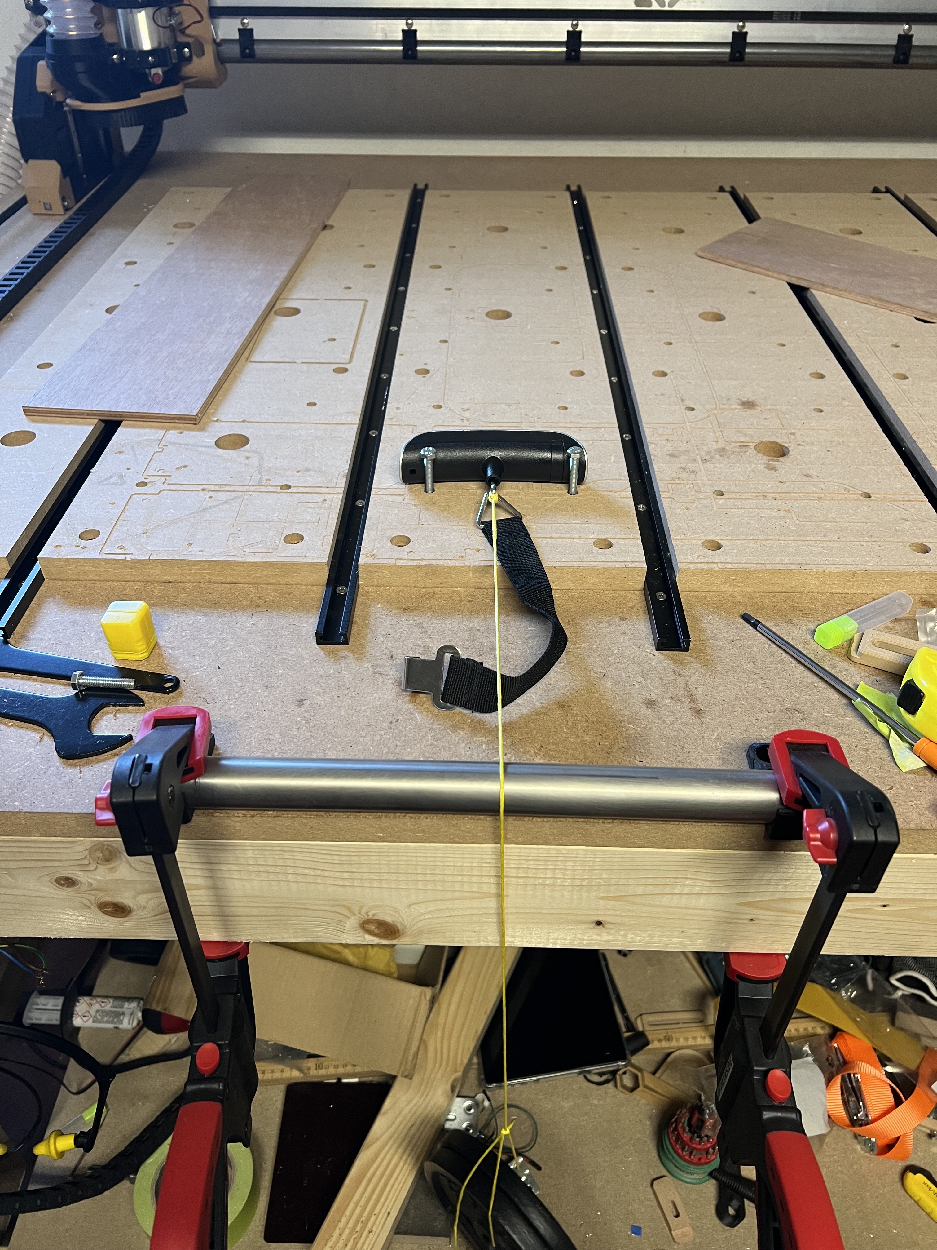
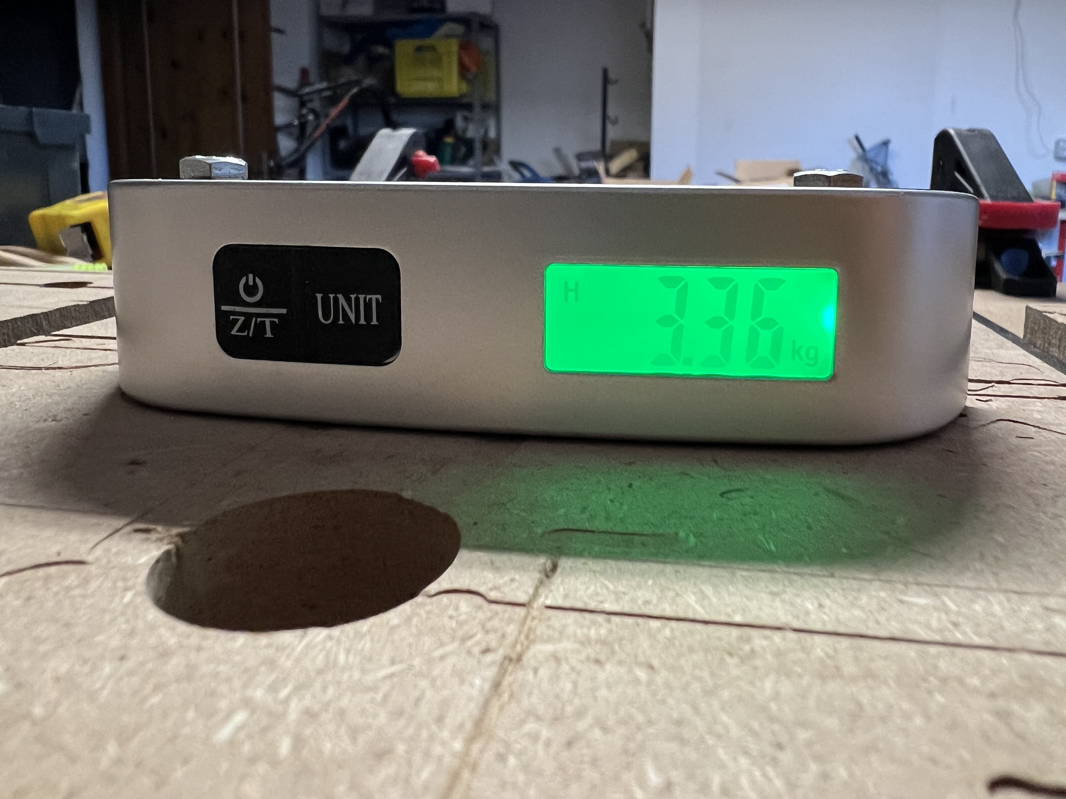
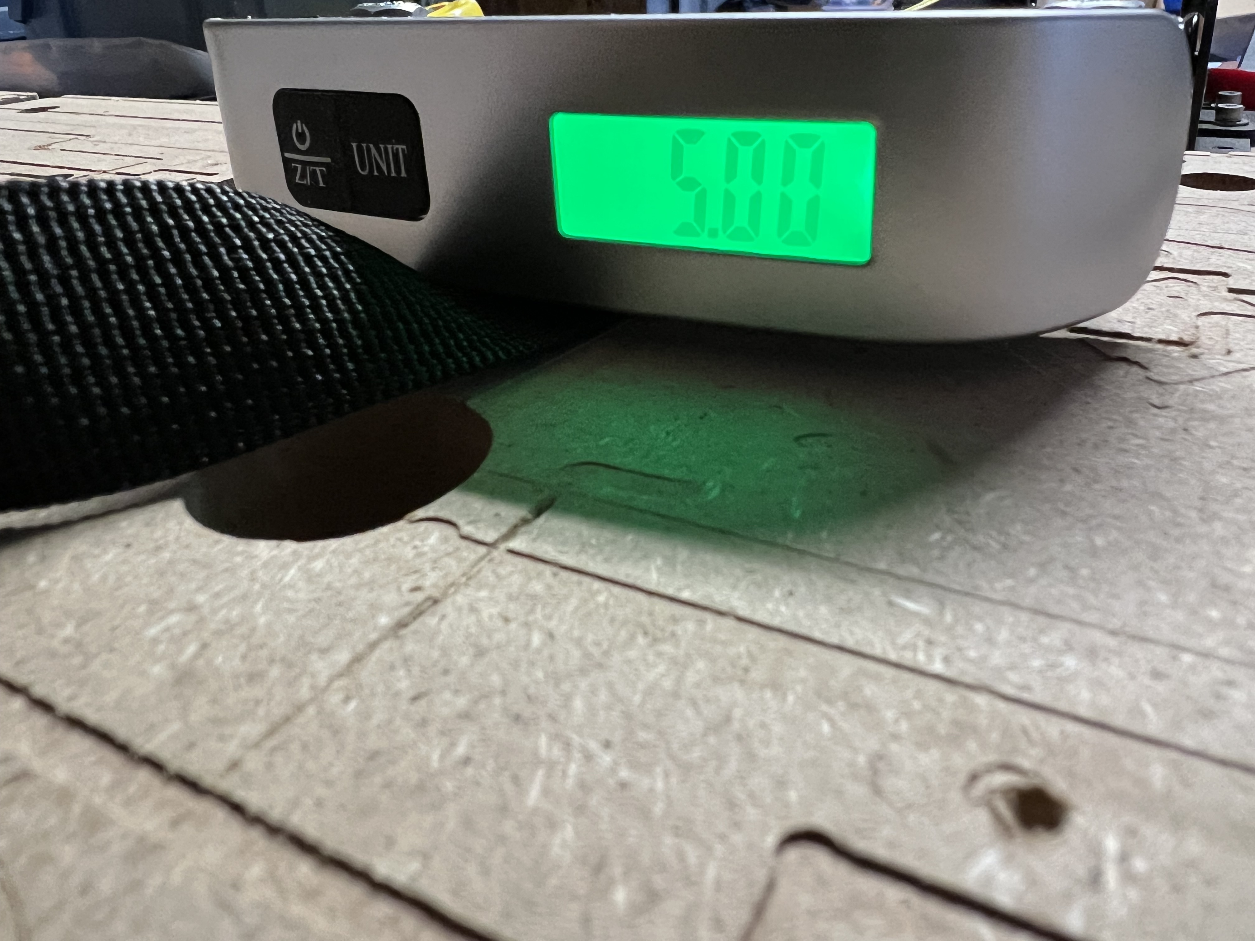
This will apply a little bit less than 4kg of force due to the rope bending over the EMT. This may be “good enough” for these purposes. Putting a force gauge between the spindle and the EMT would tell you how much force is lost and allow you to compensate.
All measurements here are relative, so I don’t think it needs to be super precise, it just needs to be repeatable. If it’s 3.8kg of force each time then the comparison holds the same, relatively.
We don’t have a good absolute measure for the force we need to handle via the cutting tool, so it’s less about exactly how much force produces how much deflection.
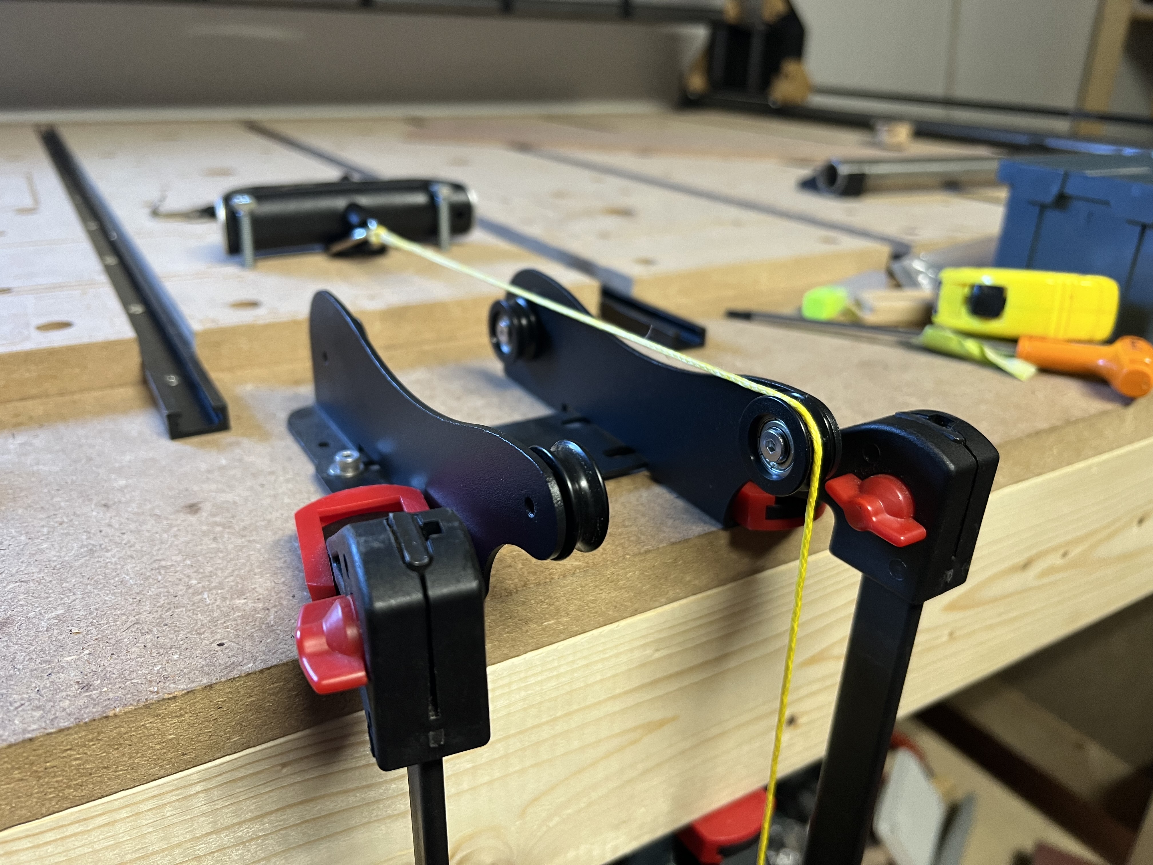
That’s true, I’m using a Dyneema cord that’s really stable and slick, and creates low friction, and used the same setup on each test to be comparable.
The real applied force is about 3.4kg and seems to be a realistic value anyway, cause it’s close to what we will generates during normal cuts. Anyway, I’ll correct the weight and perform the test again, with a caliper instead of a ruler, and a bearing pulley instead of the tube.