The price is double here for quality PET-CF over ASA-CF here so really the value is market dependent and in the eye of the beholder. I’ve not looked in a bit though:
Personally I don’t think it’s worth the money for the use case - and especially given the size of many of the parts.
Better off using PLA and adding more walls if you want stronger parts. But I tend to fall more in the anti-cf camp.
There are too many poor examples of cheap CF filaments on the market that have a very small window of acceptable print settings. It’s really hit and miss and you do not know until you have gotten it and tested it.
When print settings are off layer adhesion really tanks for infused filaments, and as a general rule cf/gf filaments will have worse layer adhesion than their non-gf/cf counterparts.
My opinion is quite often people use infused filaments wrong and end up with worse properties for a lot more money. Or they use bad infused filaments and just end up with worse properties. There are parts where it’s a game changer but you need to understand the part and the properties.
I think your recommendation of PLA is the right one for most people for the use case.
I’m using a particularly stiff ASA blend(overture/polymaker natural) and even then it’s not as stiff - only advantage I get is the temp resistance in this use case. Young’s modulous of like 2400 compared to something lie 3200 for polylite PLA from memory.
I compensated for this with even more walls and a lot more infill, because increased cross section also increases stiffness. Not because it’s the right thing to do but because I was working with what I had on hand. I only mentioned it as a side note because I do get the significantly better heat deflection temp when increasing current to the motors. Definitely not a recommendation.
One side effect minor advantage of the gear reduction is it puts the motors outboard on a separate part so you could use a more heat resistant filament and add more meat for the screws to grab and take up the slack as deflection occurs over time.
Note that godlike base layer adhesion in PET is one of the things that makes PET-CF soooooo good, and in many use cases what makes PA-CF so good. They can afford to lose layer adhesion. Having not used PET-CF though and not tested plastic deformation under load over time(slow creep) in moderate temperature scenarios - something that you tend to see can be quite bad in things like PA-CF and PETG-CF blends - makes me even more wary to spend the extra coin on it.
But for say ABS-CF - you really need to understand the directionality of the forces your part will see; and nail your fan and temp settings - erring on the side of hotter and less fan - sometimes at the expense of surface finish. Engineering / everything is a trade off - whoda thunk it……
Considered LR4 milled 1/4" or 5mm Alu plate for bulk of the final outboard motor mod design? Using additional Alu and/or printed part(s) to capture the 2:1 gear/pulleys?
So i accidentally did this. The build instructions call for number of walls and infill percentage. After loading my 5th spool of filament, i started thinking. That is based off the avg person running a .4 nozzle. I was running. 6 with fat lines. Meaning instead of my 3 walls being .4 for a total of 1.2mm, iv was running 3 walls at .8 for a total of 2 4mm. Top and bottom shells were .4mm layers instead of .2. Infill lines are .8mm instead of. 4. So without intentionally doing it, i added so much more density in so many different ways. I don’t think that it was needed, but it can’t hurt. Just didn’t even think of it when i set everything up. I just come from the tribe of printers that run big fat lines for stronger parts and less overall time.
Increasing your sparse infil width to 160-200% can be a great way to save print time on large parts too! If you have the flow to support the increase. I’m not saying this is the best option but, just my perspective - my profiles tend to us 140% or 180% - I use 140% when doing infil percentage if 20% or lower so that the infil lines are more closely spaced - this really has to do with wanting to provide a good layer for the bridging layers that form the basis for the top layers.
Also I tend to use gyroid, and overlap of one layer to the ones directly below and above it increases.
This gets deeper in to 3d printing geekery - however we know(i can link the vid of Sanjay talking about the studies in an infectious way on an interview with voidstay labs if needed) interlayer adhesion appears to be primarily a product of how much one layer touches another - and all the other settings(temp, fan, layer width, etc) are all essentially just modifying this property.
So as a general rule wider, lower layer height settings lead to better interlayer adhesion across the board. Increase the aspect ratio of the extrusions laid down by the nozzle and you get better layer adhesion. I have very fast printers only limited by flow rates. So I tend to use 0.12 to 0.15mm layer heights, 120% to 180% extrusion width depending on the feature(outer walls at 120% and go up from there), except for top surface which is 100% or less. The thinner layers mean you can use less fan which means less difference in cooling rates for different layer times - leading to more consistent dimensions (think the benchy line - when it prints the floor of the boat the layer time goes up and the hull shrinks more leading to the line).
Wider thinner layers also improve overhang quality because more of the new layer overhangs the previous layer.
Basically better overall layer adhesion, specifically also better layer adhesion for infill patterns like gyroid, better wall quality because of more stable cooling and maximising print time, better overhang quality. All good things.
So your happy accident is very happy for a bunch of reasons….
Edit: oh and of course as you say your increased cross section for greater strength
Two great things to watch regarding part strength
Tech ingredients did an amazing video two weeks ago. Worth watching for the description of how composite materials work by itself. But the results are super interesting.
He specifically tests the impact of infill density on bending strength of PLA when loads are applied to beams parallel with the layers (doesn’t test isotropy so we don’t have results yet for loads applied perpendicular to the layers, but has said he will)
Interestingly the results I interpret as exponential - e.g the difference in bending strength between 10 and 30% is minimal, but the difference between 60% and 80% infill is massive.
And here is a link to the part of the interview with Sanjay regarding interlayer adhesion. It jumps around for a few minutes from the timestamped bit but they will get in to the meat of it at 1h 2m.
Fascinating watch. I actually really benefited from listening to the whole interview - however it kinda makes me sad to watch now.
My machine will flow over 40mm/sec³ before the extruder starts to be the limiting factor. That was tested with a .4 hardened steel nozzle. Interestingly both pla, and abs flowed almost identical tests. The orbiter style extruder just couldn’t spin any faster. However my cooling will not keep up with that speed. It’s something i knew ahead of time but found causing issues with overhangs in one of my parts for my lr4.
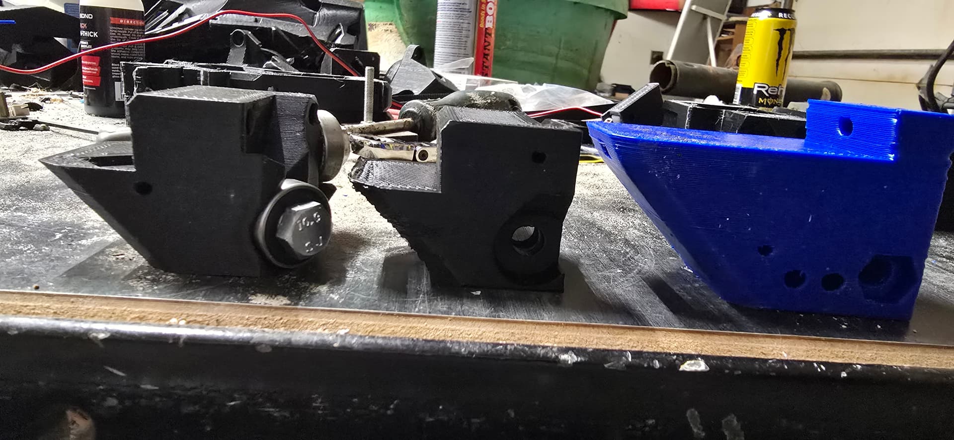
The middle one in this picture being obviously junk.
I normally limit my max flow to 25 cubes, but found i wasn’t able to cool that much in an overhang and had to lower my layer heights and slow down for the overhang to cool while printing the rest. The issue only showed up on that part and likely because it’s the smallest giving it shorter layer times and less time to cool. If i were to take a guess it was only doing roughly 15 during the overhang to print nice and pretty. I guess i could have added aux cooling considering it’s pla, but with a flying gantry it’s a little tricky to get aux cooling really nailed down.
In my testing I have seen best part strength when using about 70-80% of maximum flow for a given hotend, so setting it to. 25mm3.
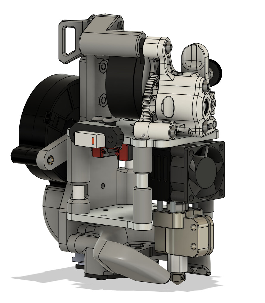
You say flying gantry so I assume 2.4 or SV08? I designed the Fourbie mod(Fourbie/Fourbie v2 at main · MakerBogans/Fourbie · GitHub) - mostly to get improved balance on the hotend and AWD since people wanted it. I decided rather than reinventing the wheel with the toolhead I would start with a vz printhead as the base and I am glad I did. As far as toolheads go as I believe the biggest limiting factor for performance on the 2.4 is the toolhead and gantry balance - essentially the same thought process as lowrider - reduce the moments and get more performance with less expensive components. Also just where all of the forces run in front of the gantry extrusion is loading up the xy joints - forces are in the wrong place.
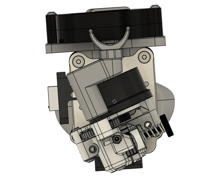
My toolhead now only shares its DNA with the VZ toolhead - and the ducts and cable stay remain the same. Because why change the ducts. But its essentially a mod still rather than a new toolhead. I just worked to further improve the ballance and get the centre of mass as close to inside the mgn rail as possible. I didn’t quite get there with this version, but its damned close sitting on top of the carriage.
(COM is that little sort of checkered dot in the middle of the screen)
I mention this because I was blown away at how much more effective a single 5015 is using the goliath duct(not using with goliath) than in the voron toolheads, and I am getting similar cooling performance to dirty bird which is twin delta 4512 - it should be worse. However only specifically with the GDSTime ball bearing 12v fan overvolted to 24v(yes, this fan can take it) Very interesting. At least for me
PLA can work ok on the 2.4 with the panels off and its not a terrible idea to just run a desk fan vaguely pointed at the printer to cycle the local air for cooler air. Doesn’t have to be a tonne of flow. Thats a pretty hacky approach but… if it works…
So off topic… but thoughts on printing PLA are still lowrider related, right?
I have a design for a totally different toolhead that should give me a lot more flow and even better balance, and (fingers crossed) much better cooling. I just have to mill and test it and I keep getting distracted with other projects like building lowrider
It comes factory with a 24v 5020 with a 4010 as aux cooling. I have a different duct in place but even still the cooling is the weak link. I’ve looked into a few of the 2.4 toolhead options, but nothing really blows my mind to date. One of the things I’ll be machining once my lr4 is ready and i have enough experience is an all metal gantry (kinda like the monolith) and ditch the 2020 extrusion. The ice cream sandwich technique the croxy guys use might be my first step in that journey. But i need to finish the lr4 and then i can start looking at the redesign of my working without issue machine. Once i can reliably mil out parts, i may also look at building my 500mm³ croxy machine that I’ve been kicking around for a few years.
Some really intriguing ideas in that toolhead assembly.
Should be a fun progression. Crossed gantry designs don’t scale super well to that size with any of the designs I’ve seen or played with from a performance standpoint. This is because gantry weight increase with size higher than other solutions. But would be a lovely reliable machine and that does scale. I had 1500h of basically maintenance free 15 to 20k acceleration(higher for infill) 400mm/s printing on the k3 with essentially no significant mechanical maintenance before the bearings gave out. That’s a 180mm machine. You won’t see that kind of performance from a 500mm machine but given it will be printing slower, you may get way more hours. The very linear forces in the motion system and ahort(relative to build volume) belt paths are well suited to reliability. Metal gantries - while again have little positive impact on speed - fantastic for reliabiloty(reduced mean time between failure). Will be a very cool project indeed.
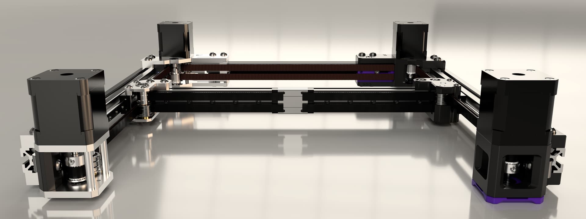
I think I mispoke… the metal gatry stuff is really me replacing the plastic parts with machined versions. This is the monolith project in the picture, but the idea is to do everything like on the left. Holding belt tensions better, and added rigidity. Who knows though. Its all just an idea I have been kicking around for a long while now. My 350mm SV08 very rarely leaves me wishing I had a bigger machine, so it might not be worth the hassle.
I once had dreams of large machines. Then I started calculating the plastic costs and decided against lots of my use cases for larger things work better with hybrid cnc and 3d printed construction.
What I’m finding is that one axis being bigger makes more sense than all three. You can increase the y travel without changing the x gantry. You can get way more z travel without losing anything on the x and y. And like i said, 350x350x350 has almost never had me wishing for more.
This is true. I have a part i want to make for my jeep. It would need 450mm x 350mm to print. I can cut it out of aluminum and have a better part overall.
Super late to the party but I wonder why you chose to put the ATC to the side instead of in the back where it would not have an impact on gantry rigidity.
Btw, I wanted to test your gear reduction for enhanced force on the motors. Do you have those available/are willing to share?