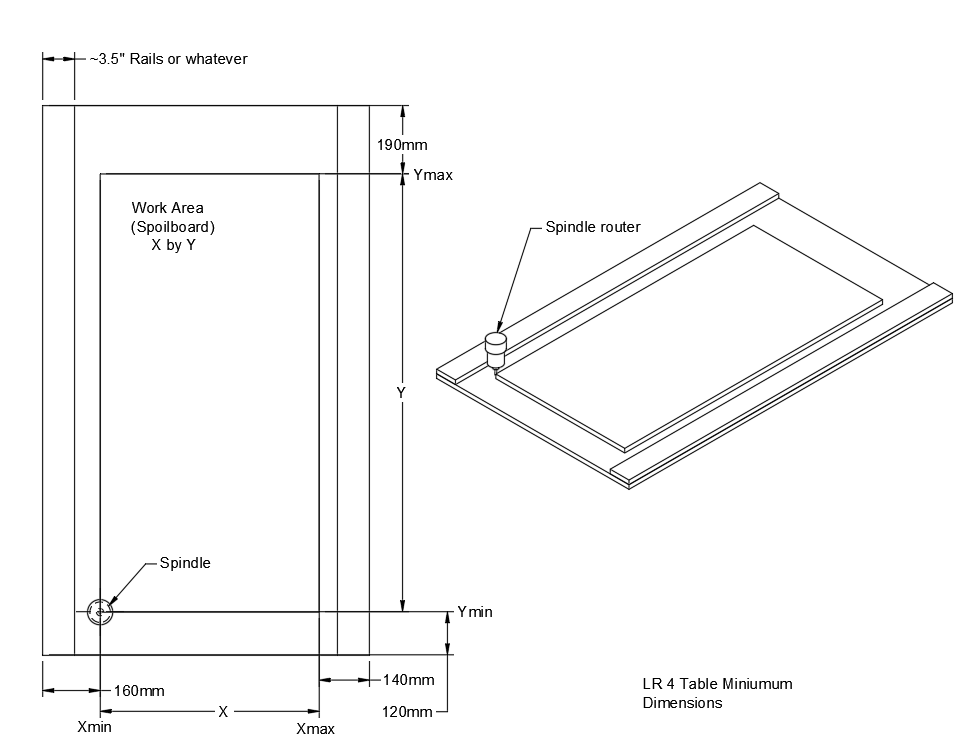
I’m designing a table for an LR4 and need to place the cutting area/spoil board along the Y-axis before the machine is built. Can someone help me understand how far the bit can reach from each end of the table? In the attached picture, I’m looking for A and B.
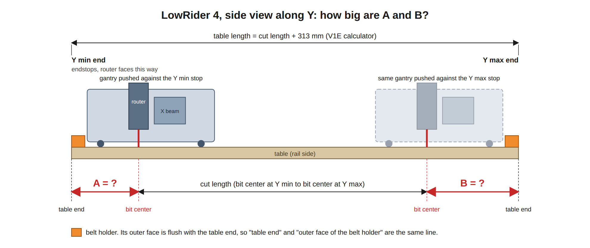
Why I’m asking: I’m building a modified version of the Mcunn knockdown setup and Menace’s update, both of which position cassette-like panels along the Y beams to support the spoil board between the beams. I’m trying to bake as much of my design into Fusion as I can before I get table parts cut on my library’s makerspace CNC. The LR4 table calculator gives ytable = yUsable + 313 mm, but not how that 313 splits between the Y-min (endstop) end and the Y-max end.
More details on the ask: With the gantry pushed against the stop at each end, how far is the bit center from the table end (the outer face of the belt holder)? This came up in the Torsion LR4 table generator thread ( [this forum]/t/torsion-lr4-table-generator/48849 ). The generator assumes the cut area is centered along the table, so A = B = 156.5 mm. Zach said there (post 48) that the centering assumption turned out to be wrong, and that he fixed it for X (157 mm on the flat side, 133 mm on the tube side) but didn’t have the numbers for Y. I couldn’t find them anywhere else either. Could someone pull A and B from the LR4 CAD, or could someone with a built machine measure them?
Thanks in advance.
Mcunn’s table: [this forum]/t/portable-lowrider-in-annapolis/27500
Meance’s update: [this forum]/t/portable-low-rider-based-on-mcunns-great-design/31135
Sorry for not including any working links; the forum won’t let me post with them