Hey does anyone know why @vicious1 doesn’t share his Step files or am I missing where they are?
Also Ryan I need to be clear you DO NOT need too but for the sake of remix it makes it much easier and reliable
Hey does anyone know why @vicious1 doesn’t share his Step files or am I missing where they are?
Also Ryan I need to be clear you DO NOT need too but for the sake of remix it makes it much easier and reliable
Step files for some commonly remixed parts have been kindly shared by Ryan, but most are not for reasons… Original Step files for easier remix - #6 by vicious1
Personally, I import the .stl files if needed to help visualize how assembled parts will look (because am designing a table, or mod).
Curious, what are you trying to do?
EDIT: fwiw, dug around Ryan’s Printables models that have 1 or more .STEP files (not all LR4 related)…
Burn the heretic! ![]()
![]()
![]()
![]()
exactly all this. I didn’t color scheme when I built my LR3, I just used whatever pla I had and I really wanna do different this time and would like to visualize it. I also made some very cheap (low effort) files for my “Mods” that; now that I know 3d modeling better wanna spend more time on and as I do like tinkering, “re-modeling” everything can be very time consuming.
but none of it is detrimental. It mostly spacing everything in CAD appropriately for easy remix is what I am aiming for. I 100% understand Ryan’s reasoning
[enactment of how that’d go]

If you just want to place the parts colored/and assemble them in cad: import them to SketchUp and soft the mesh faces. A fully lr4 asembly eats up a ton of RAM
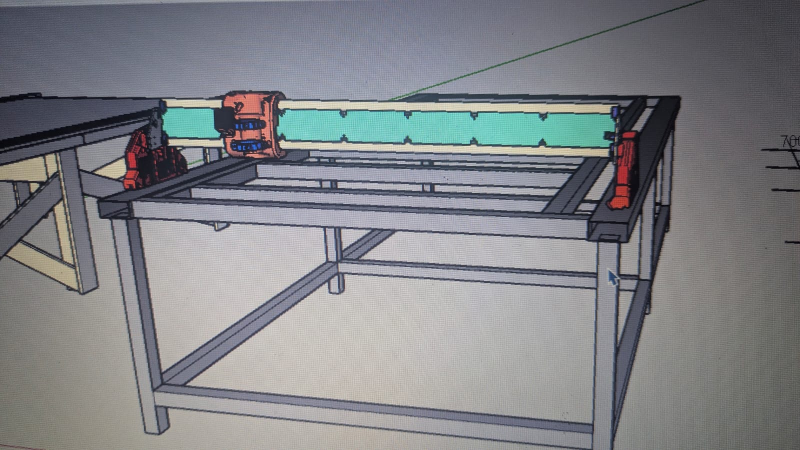
Its rough but I’m getting there, Nothings is appropriately attached and in no way am I doing the hardware but this is close to everything I need. Just gotta align a few more things ![]()
idk if its just a freecad thing or maybe a ignorance thing but alignment sucks
Can you share your file when it’s finished? I recently completed my first build but was similarly disappointed to learn the CAD wasn’t available (no, STLs don’t count ![]() ) and would have really benefitted from a complete assembly like you have there.
) and would have really benefitted from a complete assembly like you have there.
For example, designing and measuring a table is hard at this point without having assembled the LR first. Yes there are OnShape files for tables (and some Fusion files for the old LR3), but I found it difficult to setup for my build’s dimensions and then also figure out which are the important measurements that must be maintained across designs.
@vicious1 will have to chime in here, but my understanding is that taking the STLs and using them for mocking up assemblies, or even reversing them yourself into your own personal CAD is fine. Using them yourself for your own purposes that are not reselling LRs or the design files is also OK.
Redistributing those reverse engineered CAD files, though, is a license violation as I understand it.
Yeah was just about to say. I technically haven’t re-engineered anything but the aluminum plates which was easy from the dxf obviously. Everything else is just a stl mesh and I have aligned in the software. But I wouldn’t be comfortable until @vicious1 gives his input.
I did mine in SketchUp and worked out just fine (except my 16gb of ram cried)
Sharing stl assemblies is fine, but… we have already had several incorrect assemblies shared on the LR4. So I highly recommend you do this yourself. If you look in another thread we spent 3 days checking the calculators, my personal cad, the stl’s that are shared…all because of an incorrect assembly, that was being used to build a table.
If you change the parts to a different file type errors can occur, important details can be lost and that is not good for anyone.
I was pretty sure all the vital dims are already shared.
I understand it would be super awesome for me to share every thing but in the end it just makes me turn into an error checker, or some sort of license cop, and I have to explain my CAD in great details to a variety of people. I just want to make fun things for now. Experienced CAD designers can usually very easily discern any info needed and make good choice for options they share with the files provided. If the new system or shipping hardware works out and I have more time I will toy with the idea of sharing more files.
Not to sound like a super punk but making full assemblies including steppers and things that I am seeing is something you do for fun, there is no other reason to do it.
No and I agree your reasonings are sound and as stated the practical use of this is very limited. I am 100% honestly getting ahead of myself trying to figure out things I am going to design and wanting a “short cut” if you will where I can easily try different iterations without doing tons and tons of measurements, etc. Its all making it more complex than it needs to be for the sake that I am impatient and want to design stuff now vs later once my shop is clean and my LR3 is converted
I think what I refer to with “published CAD files” is different than what you’re talking about here. I only had in mind a step file of the complete assembly, no sketches or design history, merely a bunch of solid bodies. A step (hehe, CAD pun) above separate stl files.
It’s certainly not my desire to increase the support burden on you and I can understand the hesitancy.
It’s just I’m a visual learner and being able to fly around a complete model (even for the purposes of color picking) is a much happier place for me than a long list of instructions with photos that might not answer my every question.
It’s been asked and answered a hundred times already. Sorry that you don’t get a step file assembly. But it isn’t happening for the LR4.
The only dimensions that I struggled with on my recent build were where to position the Y belt clips on the table. I actually spent two nights figuring it out and double checking my work before drilling holes in the table for them because I wasn’t convinced I was putting them in the right locations.
This was partly due to the docs being a little sparse on how to position them and the images provided being a little less than comprehensive. And partly due to there just not being measurements given that I could find.
The docs say the Y_min can be “Done from the calculator or using a piece of belt on the table to set a one belt gap width.” But all I see in the calculator is a belt length and table size with no clear indication how the table size relates to the belt clip.
I wound up drawing out a lot of dimensions on my table in pencil and carefully triple/quad checking them then using one hole to initially mount my belt clips to make sure they looked sane.
It worked…but it was definitely the most frustrating part of the build for me. And I’m still not sure if just rewording things in the docs and maybe adding some more images would help…or if there’s something else that should be added to the calculator to make it easier. (If the table dimension are also the outside edges of the belt clips than making that clear is probably the easy solution.)
Definitely, still working on those docs. Scrambling with importing these days. To translate what that means, maybe y’all can help me word it better.
The calc gives you the exact outside dimension of the belt holders as the footprint. The other way to do it is make your build then add one belt spacing from each side, as shown in the instructions, to position the clips.
I feel like the belt side is clear, they are flush with the clips. The other side is the one that should be the calc distance away, table size.
Which is why I’m not pestering you with more suggestions ![]() (And if I wasn’t having so much fun with my LR4, eggbot, and starting a ZenXY I’d be less lazy about submitting some PR’s myself on the docs.)
(And if I wasn’t having so much fun with my LR4, eggbot, and starting a ZenXY I’d be less lazy about submitting some PR’s myself on the docs.)
That seems like perfect wording and was what I didn’t understand. Just adding that to the belt section and / or on the calculator would help clarify for sure.
Maybe just updating this text on the calculator:
This output is the minimum table required. An extra 25-50mm (1”-2”) or more on each dimension is nice if you will be pushing it up against a wall or in a corner.
To something like:
This output is the minimum table required - belt holders will be installed flush with the outside corners. An extra 25-50mm (1”-2”) or more on each dimension is nice if you will be pushing it up against a wall or in a corner and to provide some protection for the belt holders.
And on the docs add “The calculator table measurement gives you the exact outside dimensions of the belt holders as the footprint.”
Thank you!
Ryan, maybe you could sell a version of the files in a way that works for you and those that want them.
No strong feelings either way, but maybe a potential to further support the project.