Well I’m well and truly committed now …
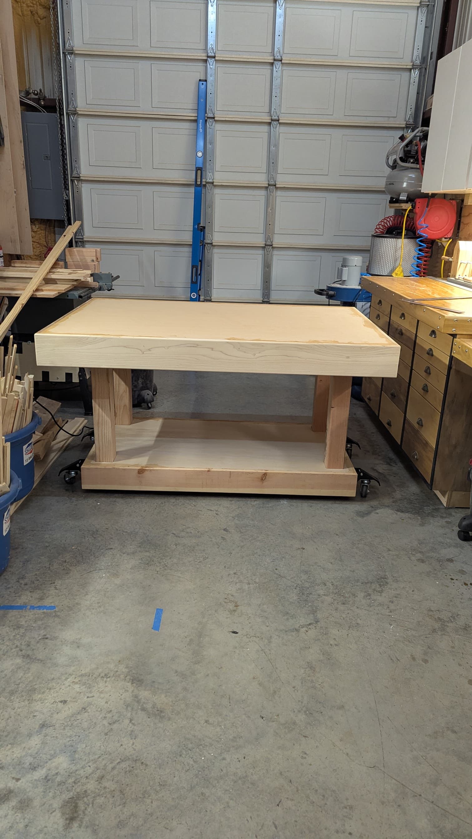
After a bunch of measuring, soul searching and rationalizing my choices (space/time/$$) I chose the LR4 because I believe I can comfortably re-arrange my wood shop to handle a 60"x40" table which will yield an approx working material size of 48"x27".
My goal is to build the largest practical size LR4 I can accommodate in my shop while ‘attempting’ to retain the potential for using it on a full sheet of plywood or other 4x8 material if when needed.
The 48" ‘x’ axis size would allow me to theoretically (via some yet to be determined means) accommodate 4x8 sheet material sometime in the future.
A secondary goal is to be able to utilize the table I’m building to provide a nice flat assembly/work surface with built in hold down clamps (via “t” track).
I know this will require the Y axis belt terminations to be made easily connected/disconnected (I’m assuming this has been done successfully… ??)
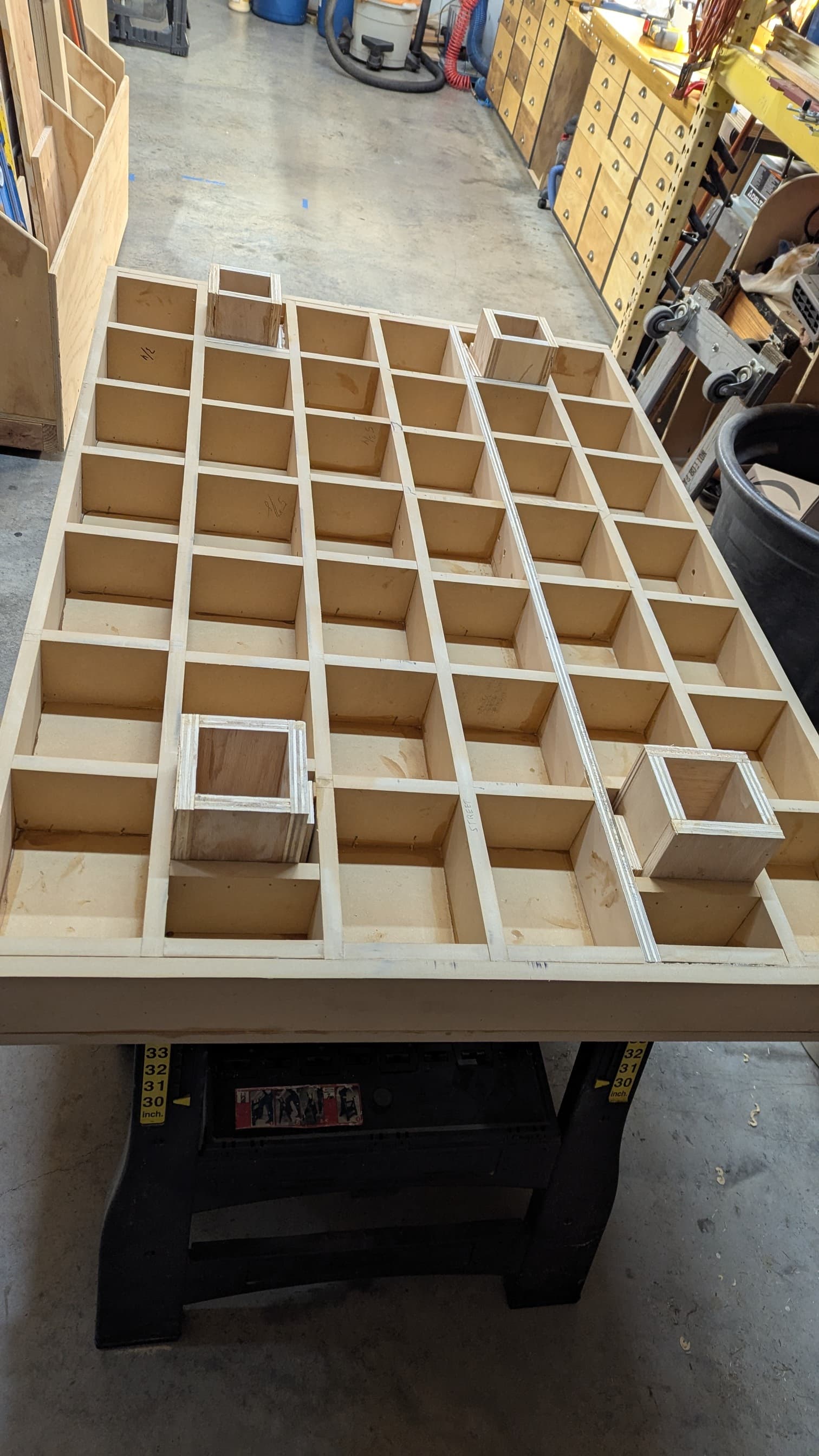
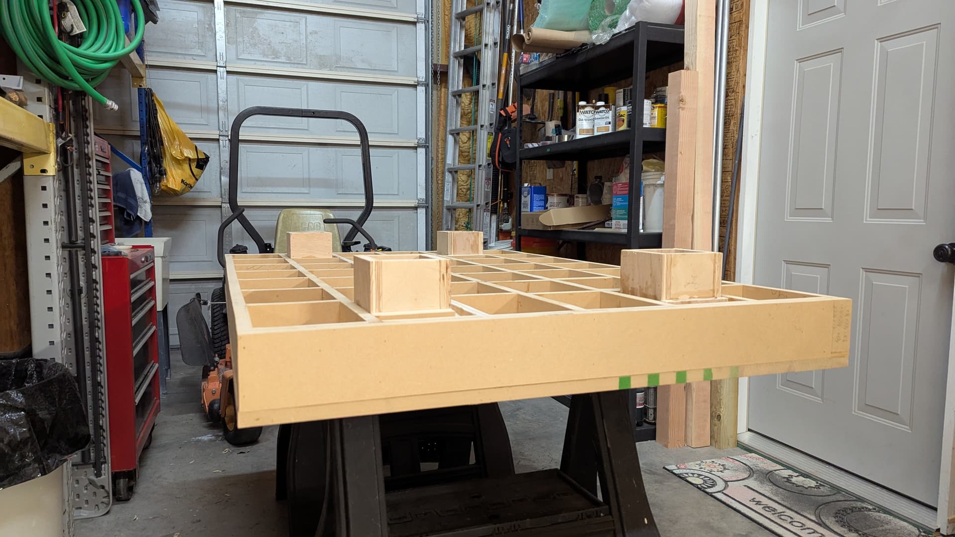
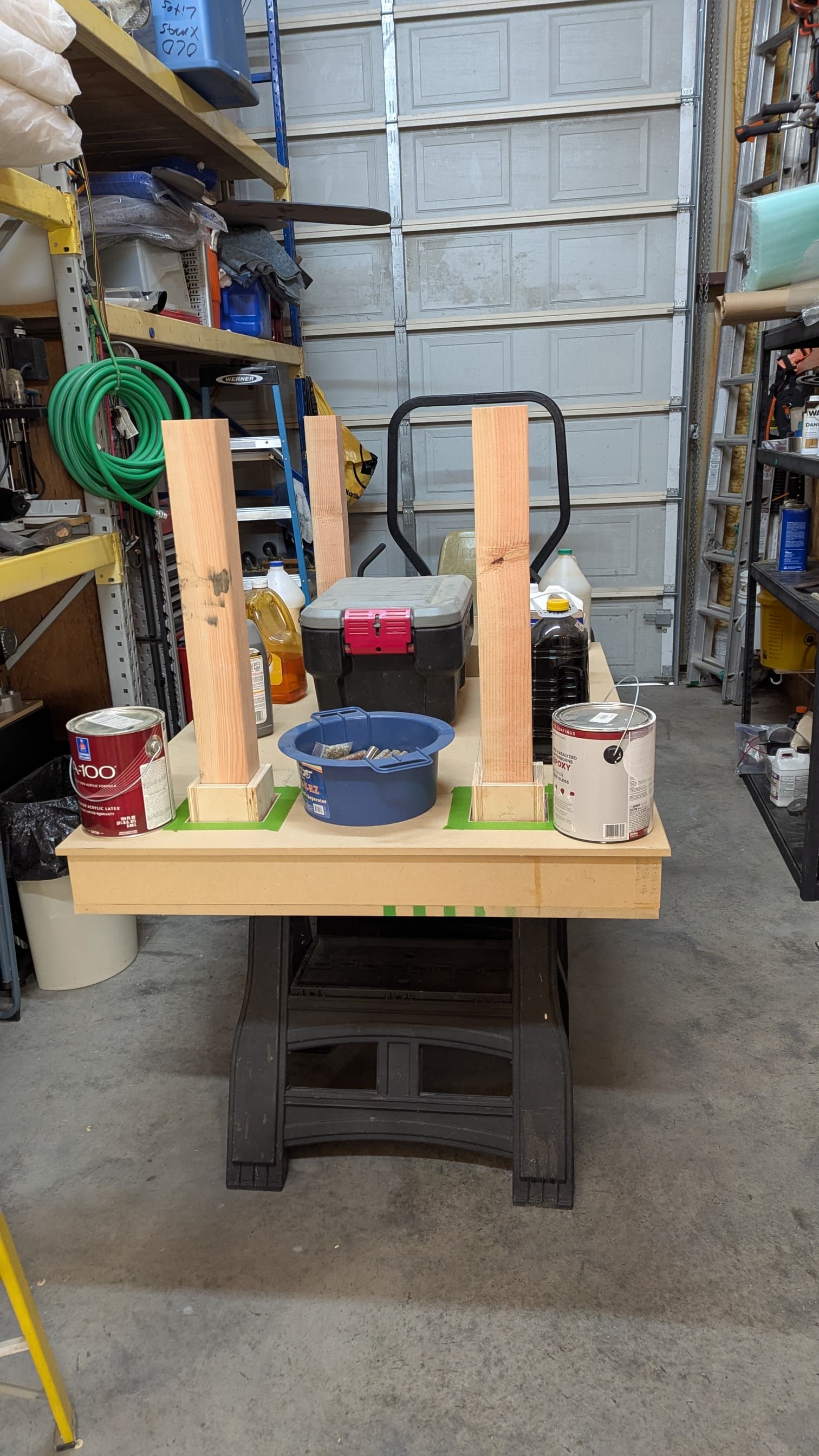
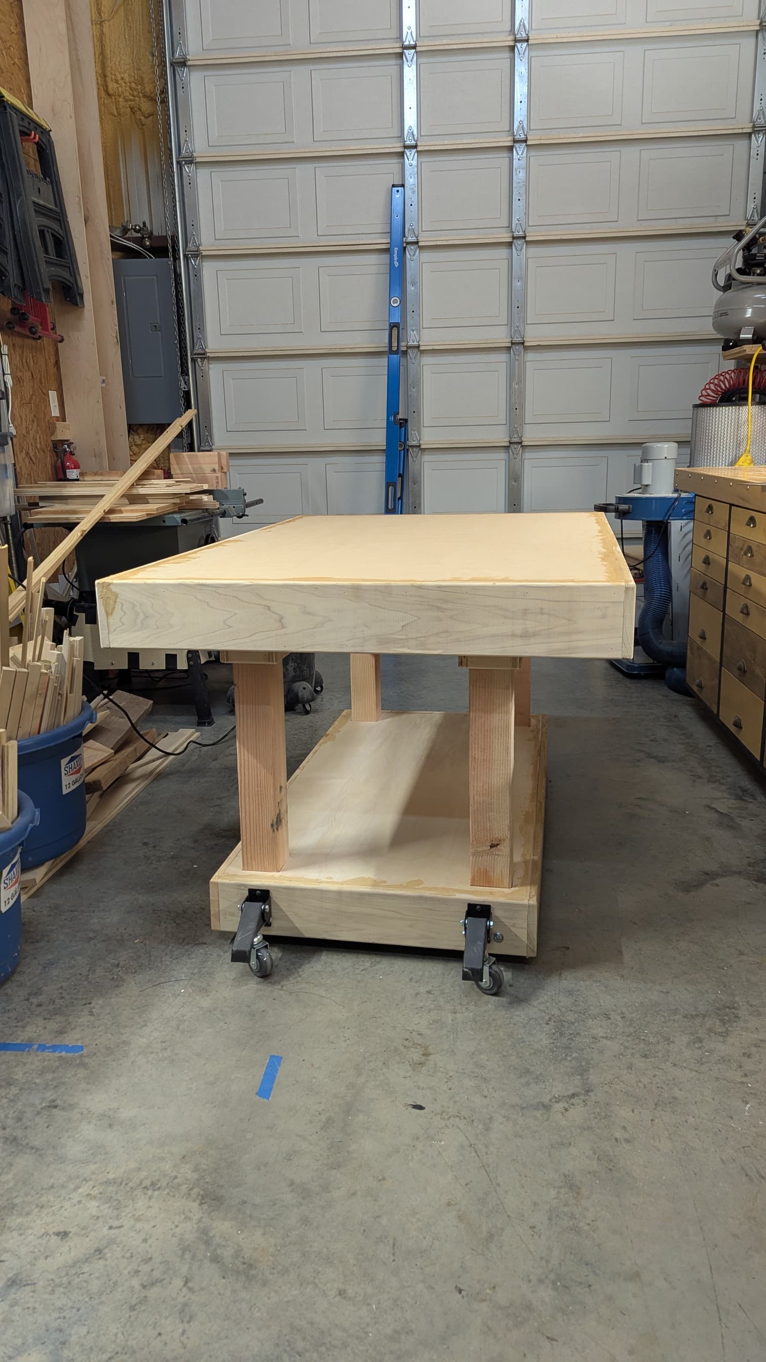
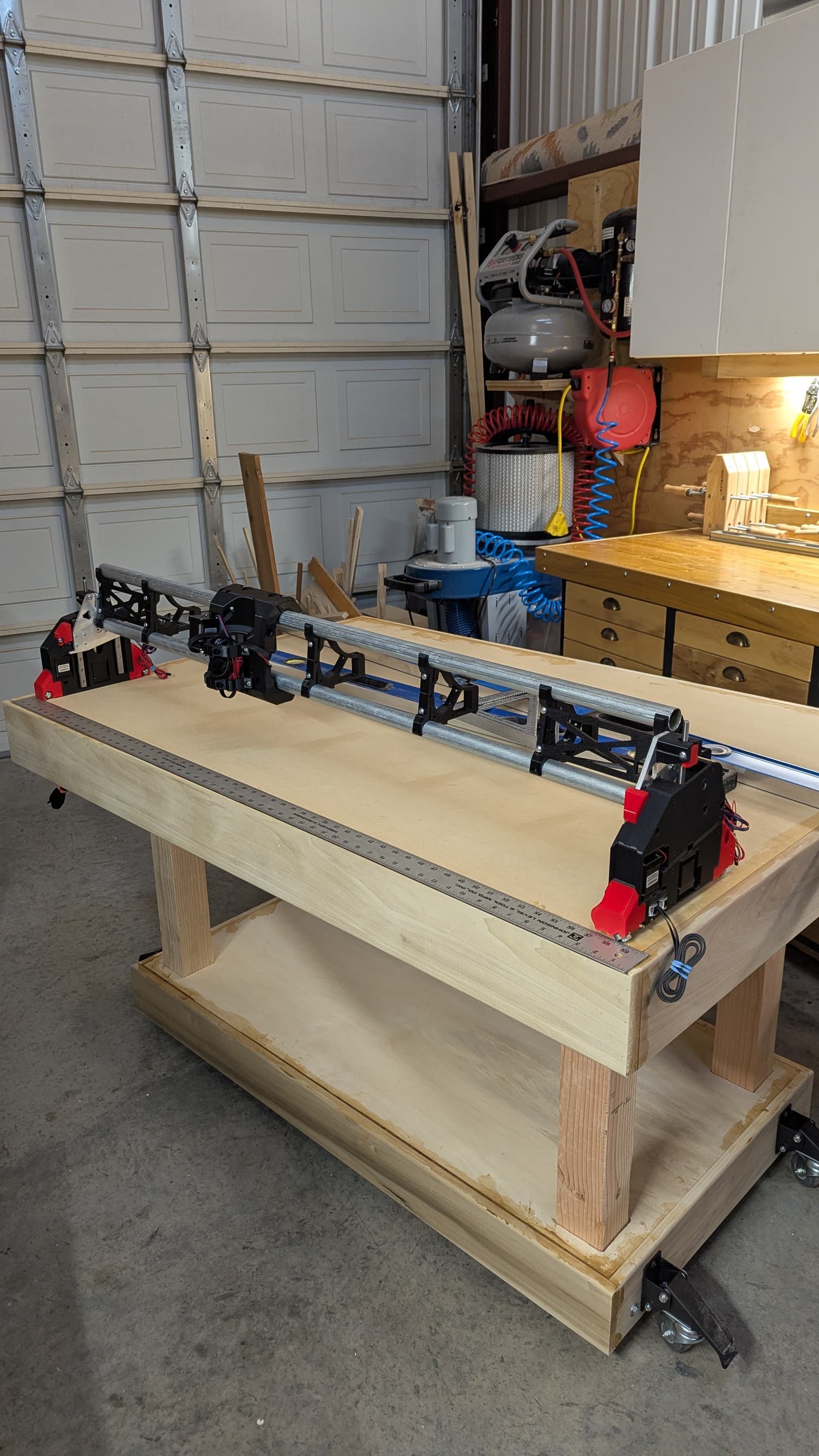
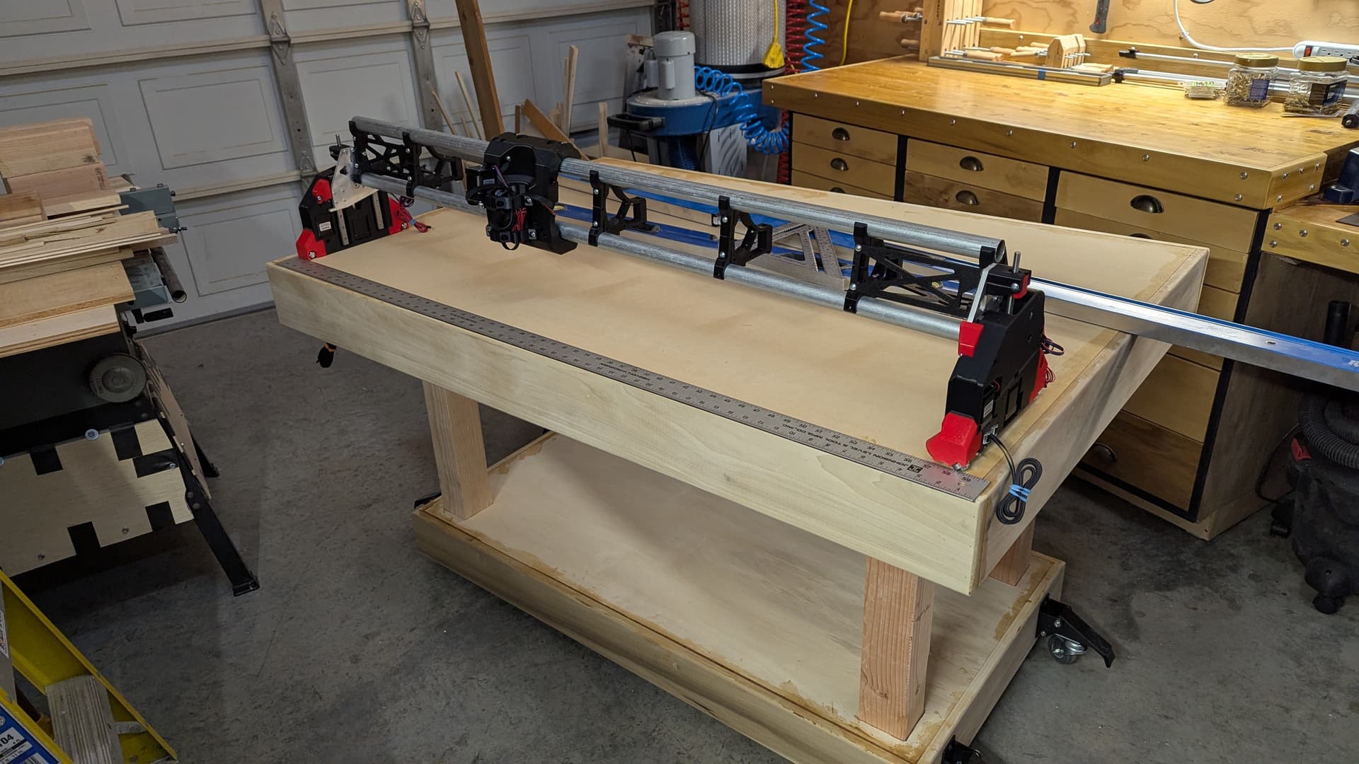
Anyway … here a few pics of the current state of things. I think I’m about ready for wiring but still need to double check some preliminary post build measurements.
Making great progress so far.
What type of fold down caster mount are you using?
The unconventional X axis being the long axis will cause a bit of workaround but it does preserve the chance to go to a bigger table. Maybe even have a temporary table that you put out for large sheet work (can be as simple as flat goods on the floor!)
Then swap back to the smaller table for everyday use.
The casters came from Rockler wood working store / shop. Those were purchased more than a year ago for another project but not used… I’m pretty sure they are still available.
I didn’t use them originally because they are a bit unsightly and a potential ankle biter when not in use. Also they were a bit pricey (Rockler is a $$$ store in my mind) but probably available elsewhere at lower cost.
Functionally they are great … if interested look for another type that is very similar in design but incorporates a bracket that mounts to the table (like these at half the cost) which the lever and wheel connect to for use. If I hadn’t already had these that’s what I’d use here. In this case the table will be up against the wall most the time and the top overhangs the bottom which will minimize the likelihood of the casters interfering with something being placed next to the table at floor level… and if it bugs me it’s just 2 large wood screws to remove them.
If you keep the machine orientation so that the linear rails on the table are Y and the gantry is X, then you’ll have far fewer issuse compared to you trying to make the long axis Y.
I think you’ve built a machine that will give you a lot of flexibility and which can support larger materials when needed.
The tale of woa would be if you insisted on making the long axis Y for this setup. If you don’t do that, then I expect everything will be fine for you.
This is an awesome build and something I’d like to do with mine in the future. I have one of those “bucket list” projects that would require a full size 4x8 work area, but most of my routine use is much smaller. I had originally planed for 30 x 60 because of baltic birch sizes in my area (1/2 sheet), but with the skyrocketing cost, I’m resolved that I should probably plan for being able to cut 4x8 sheet goods.
Awesome build and I’m watching with interest to see how it works for you.
JIm, the plan was always to keep the x axis longest if for no other reason than that the long side of of the table will be against the wall, and for me at least, I tend to think of X as being right to left as I stand in front of it or stare at it in a diagram/sketch.
This is my first CNC but I’ve had, at various time in my career years of parametric CAD design on and off, and used a number of CAD tools (being retired and cheap my go-to now is FreeCAD)… and for 2D drawing/sketching almost all of them default to x being the horizontal (right to left) axis.
I know for my 3D printer (ratrig v-core3-400) I built a couple of years ago that was typical (x being right to left). However in that case I chose to make 0,0 the back left corner (away from the front) due to the way I’d set the Y limit switch for aesthetics and convenience (not always a good reason but there it is). This created a bit of a deviation from the then ratrig default config but was a simple tweak to the machine base config file.
Somewhere on this forum I think I ran across a comment from someone that stated that X should always be the longest axis. Is that correct? If so do you know why … is there a performance or practical reason why it would matter.
Also, what’s typical in the CNC world in general. I know from experience it’s better to get onboard with generally accepted practices than to keep trying to multiply 1 by 25.4 in your head all the time
Read up on the “right hand rule” for orienting the axes. What’s key is their relationship to each other and positive/negative travel direction, not overall axis length. If you get a direction reversed, you end up with mirrored parts.