…… ![]()
1 Like
The controller may be switching the negative rather than the positive side of the circuit.
Thanks Tom. I believe you are correct baed on some scratcbing around i have done. However, not being an electronics person, I battle to fully grasp what i read. One thing I did find that could possibly resolve my issue is setting the output circuit to simple on/off via the configurafion file. At leazt this what i understood but could be totally wrong. I was hoping to find a simple step by step how to for dummies.
Had an identical situation using gpio16 to power a fan via a buck module. After changing the fan with an exact new one, all worked as expected. Have no idea what i did electronically but it worked. Now i am having the same problem trying to switch the relay.
Any assistance for this dummy would be greatly appreciated.
Jackpot V1 and V3 are low side switched.
Your loads have to be hooked up so that the + and - go to the jackpot output. You can’t hook up jackpot + only and then tie your load’s - to the power supply or some other ground. That won’t work. (because on the jackpot the outputs + signals are always hot, it’s only the - that gets turned on or off)
Your loads also have to be compatible with low side switching, which most stuff is when you hook up both + and - to the jackpot output.
To be sure about any given circuit, tell us what you’re trying to do and be specific, then we can help you.
I caught a bambu lab p1s ams combo unit for467.00 delivered on a black friday deal on amazon. It will print at 300mm/sec with hf pla filament. However I usually slow it down in the slicer to 105mm/sec and I also use a 0.6mm nozzle at 0.2mm LH with PETG filament. It took 21 hrs to print my core BUT I also had 5 Walls and 40% infill with creality PETG-CF filament. I also used Carbon fiber filled petg for the XZ plates and I plan to use them permanently as I don’t do a lot of production runs and will be building shop cabinets with it initially.
1 Like
Welcome to the forum @Robert144! That’s a hell of a deal on a P1S Combo! I am very curious to see how your machine performs with your filament choice. We had one in the beta test with PETG and it didn’t go well at all. Our standard is Basic PLA with none of the extras. That is proven to be the most Rigid which is what we are looking for. The only other better option is PET-CF/GF as it is even more rigid than PLA and can withstand higher temps. Good luck with your build! Start a build thread so we can follow along and help out if you run into any issues!
3 Likes
Since that post, I got a P1S combo myself. I’ve been very happy with it. Like Jonathan said, start a build thread. I have some concerns about the filament and printed XZ plates, but let us know how it goes.
2 Likes
I read that as YZ plates on his post. Good catch!
Be careful if you exceed the recommended settings. At somewhere around 4-5 walls and .6 nozzle the ‘hints’ that Ryan has in the parts stop working right.
If your core didn’t have problems with the bridging overhangs inside the cable tunnels then you’re fine. If it did, you may want to consider printing it over with the recommended settings.
For your XZ plates as folks note above you really should consider aluminum plates. We tried printed in the beta, and though you can get away with it for light duty work it really compromises machine performance. There’s a reason Ryan uses metal parts when he does.
Note also that PETG isn’t a recommended material. If, for example, you had concerns about heat softening of parts then the recommendation is to use PET-CF, which has better rigidity than PLA, where the PETG-CF does not.
2 Likes
If you want an easier way to dial in your settings, you need to pay attention to the volume of flow, not the speed of the head. So a number like 20mm³/s, that takes in account the nozzle diameter, extrusion rate, layer thickness, layer width, and movement speed.
3 Likes
I calibrated the flow Dynamic (K Value) as well as the pressure advance in the slicer for the specific filament I used. the core came out perfect with no issues all the wires slid through the tunnels and passages without any issues. I slowed down the print speed because I didn’t need the parts Immediately and didn’t want to put the stress on my printer. It makes a lot of noise at 300mm/sec, and runs fairly quiet at 105mm/sec.
1 Like
Coming back from the future to update: I’ve rebuilt my table top which included resetting the Y rail and belts recently, and I was able to get it square on the first try. I also had to rebuild my LR4’s core because my printer settings were wrong.. I stripped the old one and built the new one in like an hour or two? Pretty sure I spent a whole day on those things during the first go around. Moral of the story: practice makes better, so don’t ever give up ![]()
2 Likes
Hi Maker Jim.
Makes perfect sense to me.
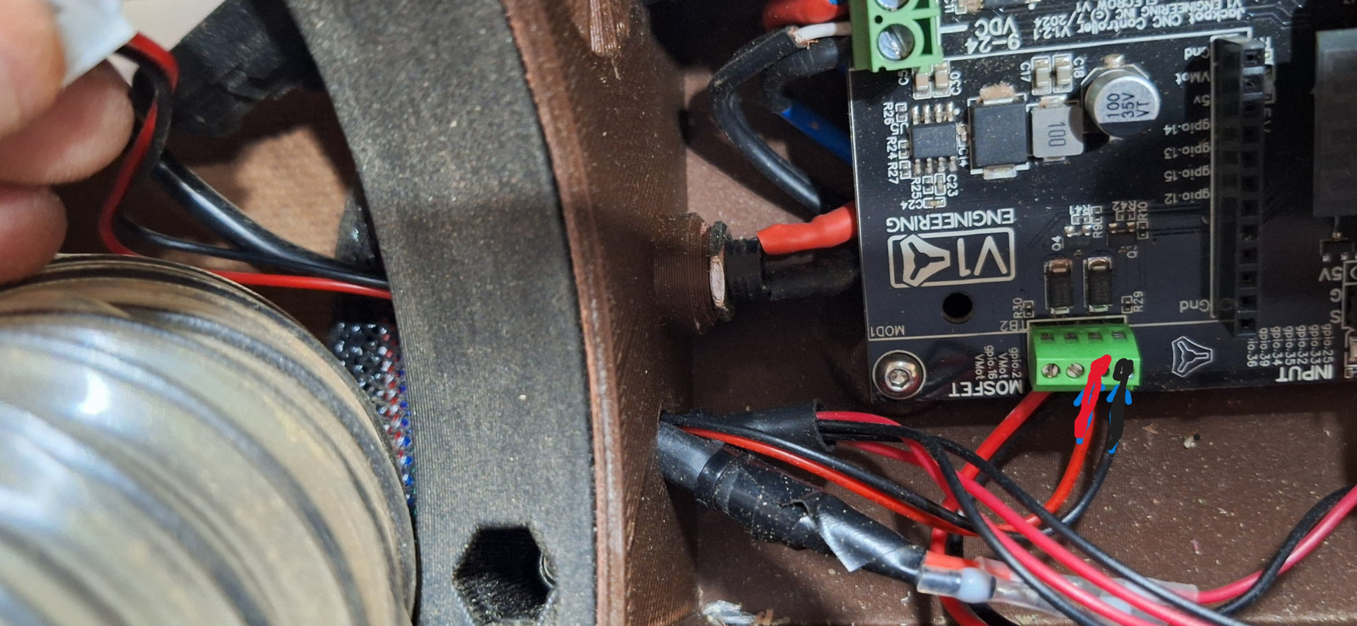
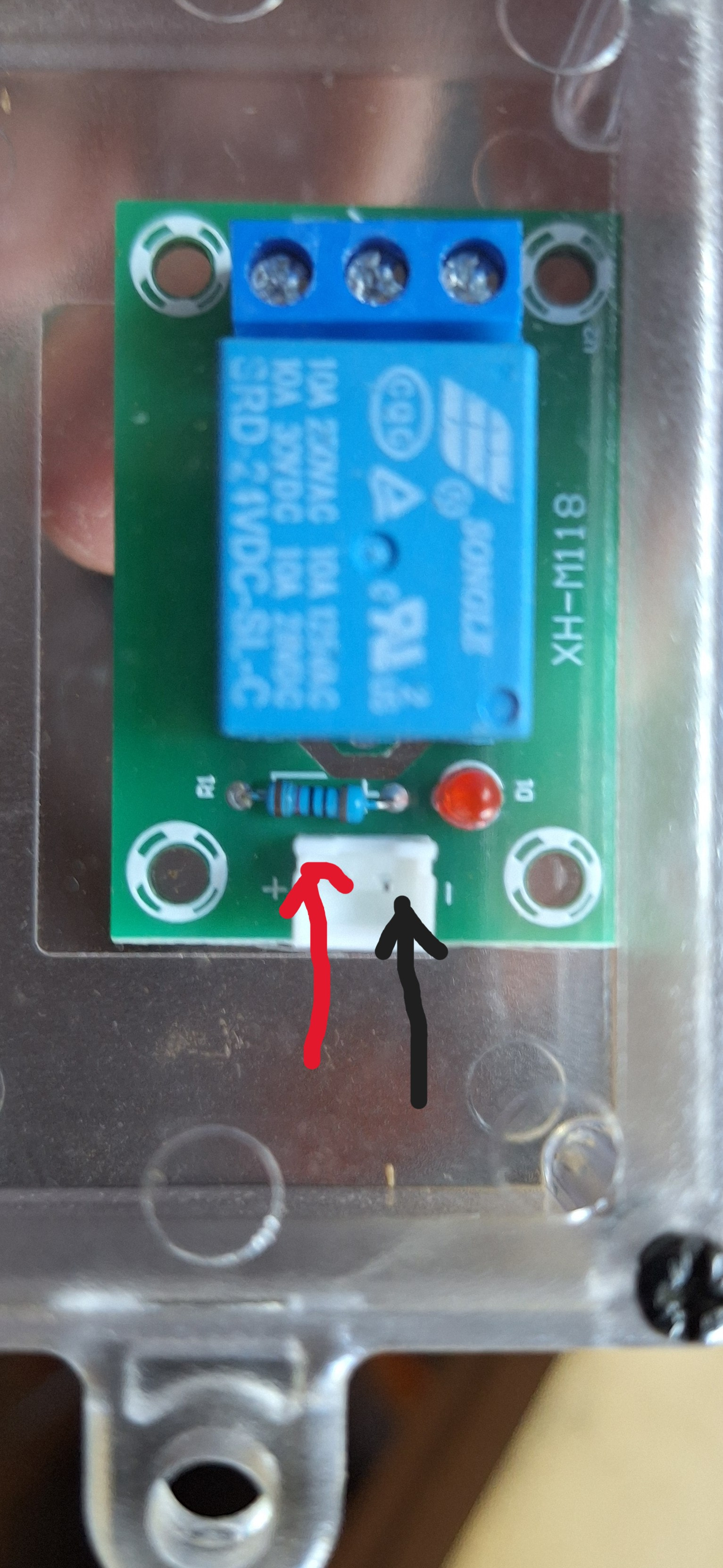
I believe i have connected as described. In other words I have connected the + and - from the jackpot board to the + and - of the relay module.
See photos below.
Currently disconnected but when connected, relay module does not switch with GPIO 2 switching.
Jackpot connection
Relay module and connection
closing old topic to help fight spambots