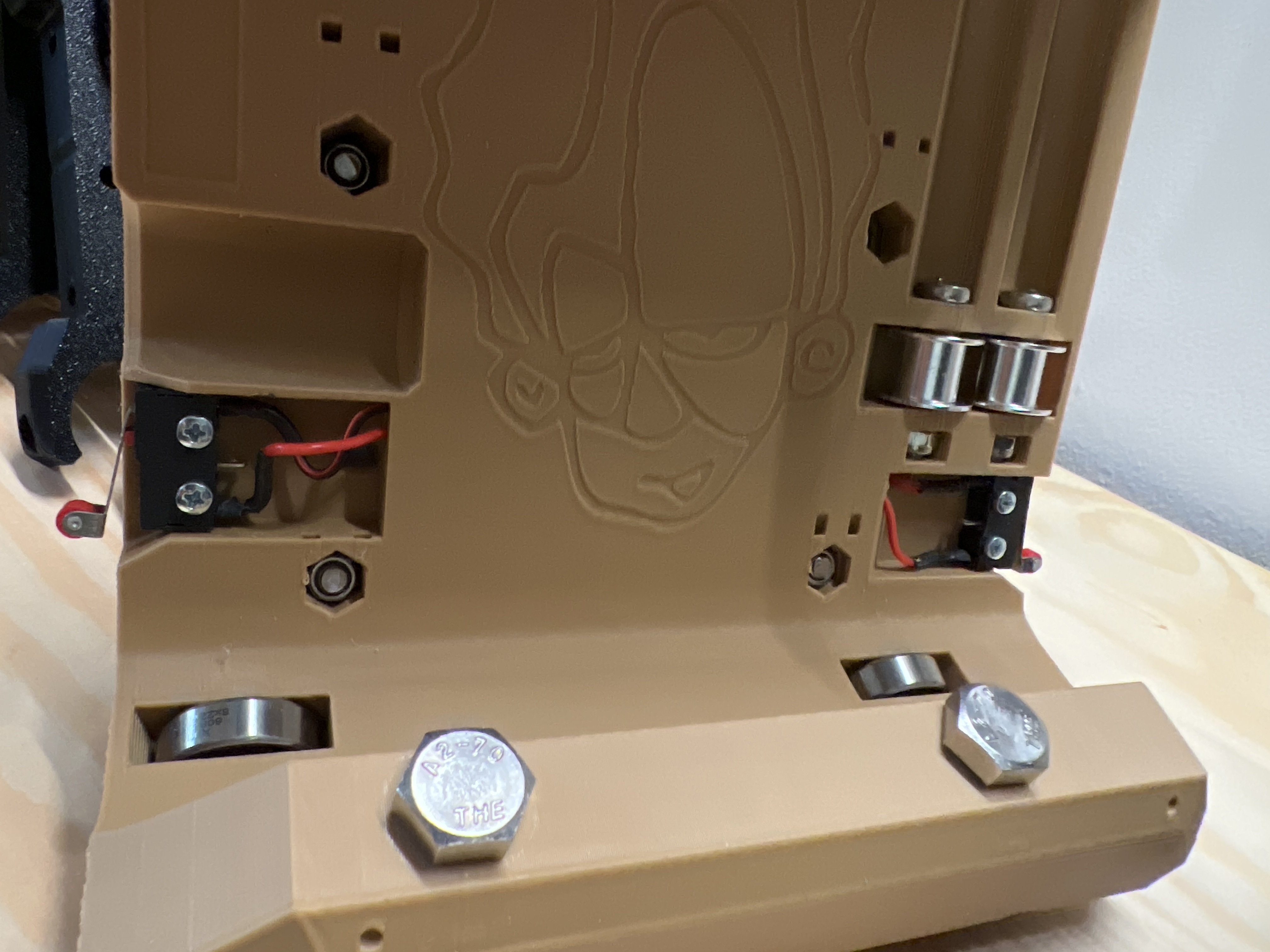
I am partway through an LR4 build. One thing I am confused about is the end stops. As near as I can tell, there is room for 6 endstops on the side plates alone (1 each in all 4 wheel assemblies + 1 in both Z-stops), and I believe there is a seventh in the core (it’s not printed yet, so not 100% certain.)
But the hardware kit ships with 5 stops. Which 5 of the 7 positions should I put switches in? I couldn’t find anything in the LR4 or even LR3 docs. Searching elsewhere on the site I saw a few references/wikis about ‘dual endstops’ but that doesn’t really describe the physical configuration (near as I can tell.)
There are alternates for people to be able to home different configurations.
The “normal” usage is the 2 Y stops under the plates in the front (facing same direction as the router) plus the 2 Z max stops, and the one on the core on the motor side as X min.
The X max and Y max stops were added in response to some edge cases where people wanted different homing options for specific spaces, or for people who wanted to use the long axis for X and the beam for Y, which have a need to home differently, or else they will produce mirror image parts. Note that the default firmware does not support this, so you will need to make edits to the configuration to use this.
I believe the construction docs will detail installation in the normal way.
Standard configuration would be to install the Y endstops in the front wheel and rail parts. And leave the back wheel and rail parts empty. And the core also has 2 spots. And standard configuration for those would be on the X min side. There is only one spot for each Z endstop
In addition to all the good information already provided, at least one maker has a concept of taking advantage of these added new slots (that in a normal build, would remain empty), and populate them with additional end stop switches, so that he can use not just soft limits, but use hard limits at both ends of travel so that even if the machine skips steps, it still can’t crash into the far end of the table. That is definitely what one could call an edge case usage. But it’s just worth noting that it’s at least an option. And this also would require making edits to the config file.
PS: since the limit switches are currently ignored unless one is involved in a homing process, I would not know how to be able to do that. But he seems confident!
My idea is to simply use this feature for better safety, and cause I want the freedom of choose the side of homing without the need of rewire things. Anyway, It’s a “free” feature, so why don’t use it?
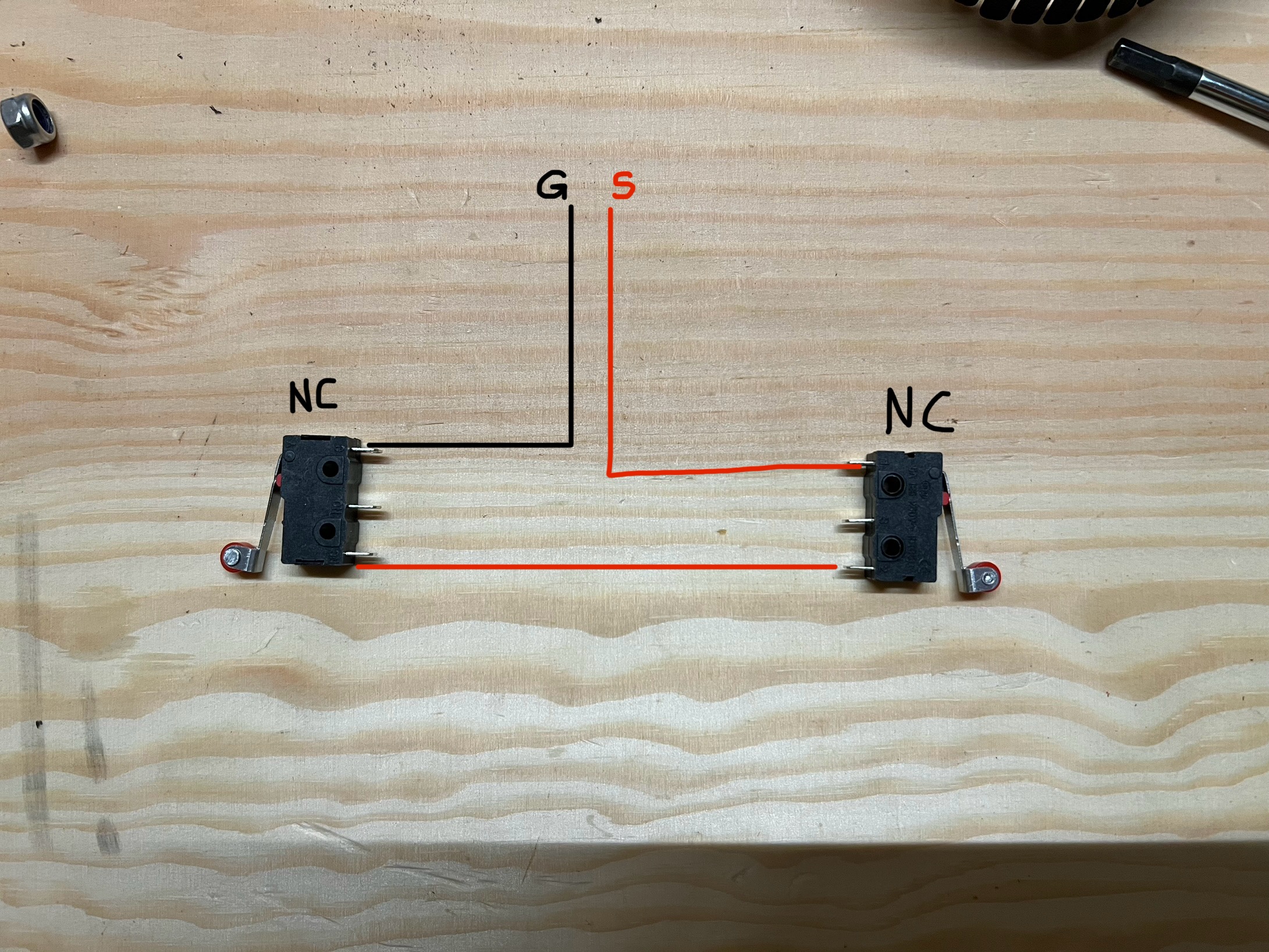
The Switches are connected in NC configuration, in this way, whichever of the two switches is pressed, the circuit is broken. FluidNC decides which limit switch is activated based on the direction of movement of the axis.
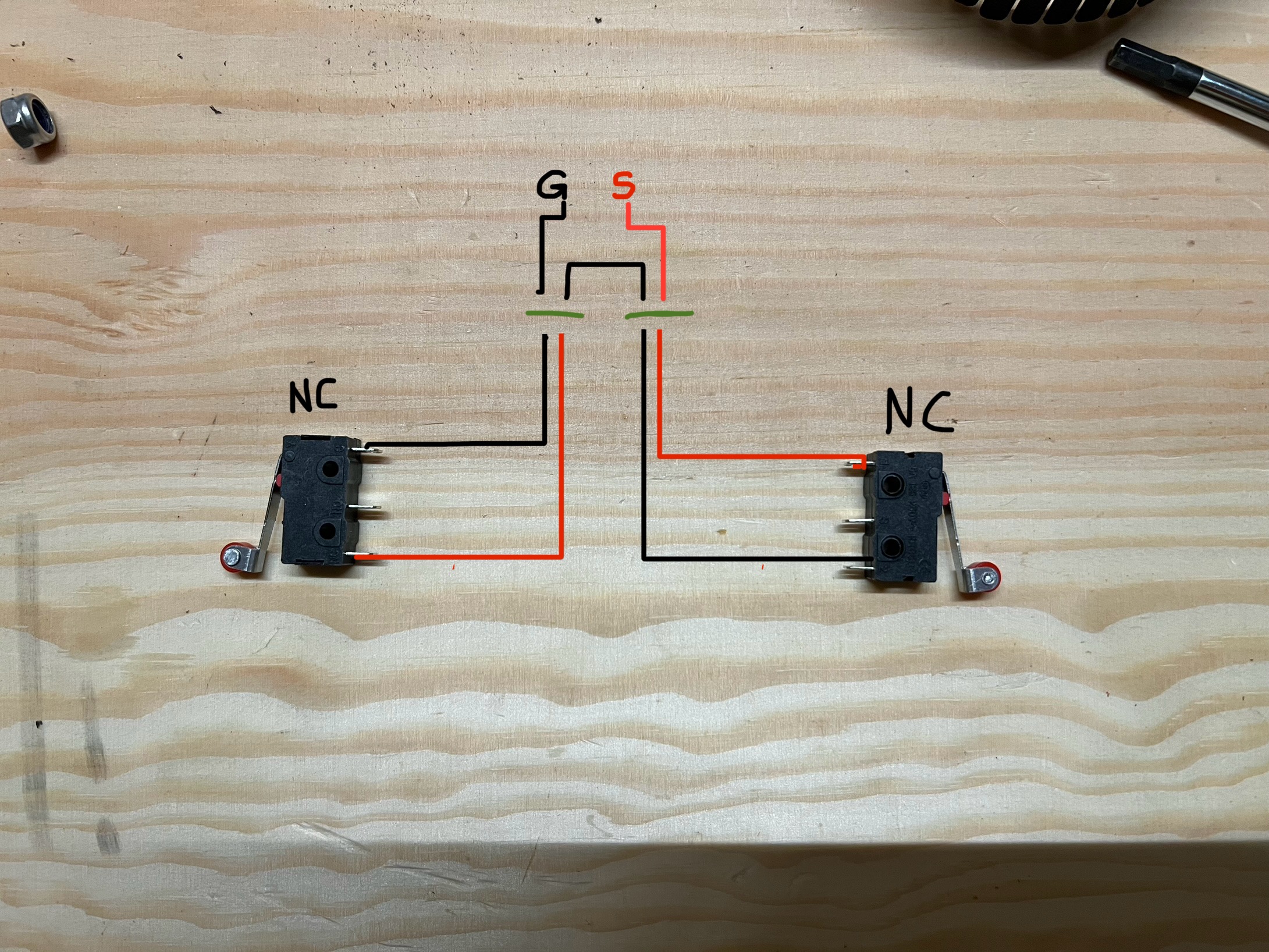
If You want, You can use standard connection on each switch, and then create a custom extension cable with double end, like this(green lines are connectors):