I’m finally getting around to converting my LR3 to an LR4. I finished up some inlay cutting boards, and some laser work for gifts and have a gap to rebuild it.
Besides the LR3, I’ve built and reclaimed the MPCNC as well as 3 3D printers. Some of the decisions and plans I’ve made are based on my experience, so new builders should be sure to construct a working machine that can draw a crown and cut its own struts before venturing into my follies.
To maintain some level of cutting performance on the LR3 during my last round of work, I had to adjust the core bearings repeatedly because of some layer delimitation near the X min top bearing. It resulted in some wear on the top beam tube that caused the movement to be visibly irregular. I also had developed some very inconsistent Z movement on the X min side that I never fully worked out. Best guess is a loose grub screw, or insufficient lubrication complicated by poor dust collection that was showering that whole portion in walnut and maple.
Features I’m keeping:
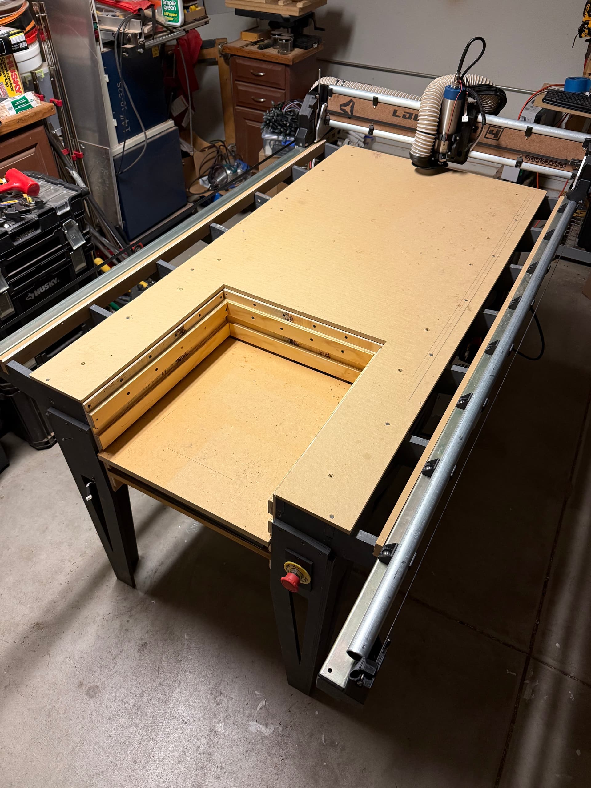
My table. (I eventually want to increase to a 48" x 54" half sheet size, but I don’t currently have room and expect to move to a place with a bigger garage at some point in the next year.)
My spoilboard strategy. I love the PVC fence and the ability to wedge things into place. I will add hold downs for jigs and fixtures to the strategy.
The kinetic tool mount for my laser. The drop table portion for the rotary and taller work.
Things I’m changing:
No more hidden belts mod. I actually had really good luck with it once I had it working, but it added an unnecessary layer of complexity and it took a while to get working smoothly.
New WLED controller for the under-beam lights. I’ve added the appropriate components onto a breadboard and based it on the newer S3 variant. (Stamp from M5)
Spindle. Not sure about this. Lots to consider. I saw an opportunity to try it, and eventually I’d like to look at some of the DIY tool changers. So, I thought I’d start the journey. I have both Makita and Kobalt options as backups.
I thought about calling the build the “Henry Ford.” I’ve decided on PET-CF as the material. This meant I could have it in any color I wanted, as long as it is black.
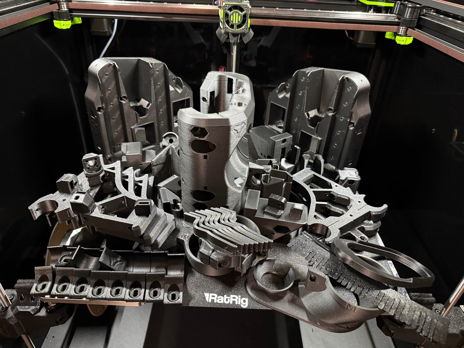
Last print was the core. I’m pleased with the prints off my RatRig Vcore 4. Definitely a luxury splurge in the last year. These were done on the Hybrid variant, although I’ve now added IDEX. The hybrid definitely prints faster with good results.
Part
Time
Weight (Est)
Core
6h11m
591g
YZ min
4h1m
388g
YZ max
4h2m
387g
braces(6)
5h35m
475g
tool mount
42m
63g
dust shoe
56m
84g
z group
1h3m
302g
wheels
2h18m
201g
z blocks (test)
25m
82g
Total
25h13m
2573g
Does not include electronics box, Peter Plates, or rear beam covers (Or time/filament for TPU bristles.)
I spent 4 hours yesterday tearing my LR3 down piece by piece and inspecting each component.
Positives
Wiring held up well. Everything seems intact. I used some very small wire for Y - endstops (don’t remember why) so that will be changed for something slightly more robust.
Kinetic mount and Router Mount held up well and were still very tight. Tape used to shim/tram the router was still in place.
Undermounted LEDs were in very good shape.
Problems Identified
Core cracked / delaminated in the area of the top bearing mount on X min side.
X min brace was cracked and the top EMT was loose.
Idlers for the Y belts are caked in a grease/sawdust compacted goop. Cleaned these with Simple Green and it did come off eventually. They still seem to turn freely.
The two rails on the YZ min plate were bound up severely. No smooth movement at all. The “front” of the two barely moves at all. It feels like sawdust caught up in the bearings, so improved dust collection is absolutely necessary. I’ll clean the rails today to see what I find. I purchased new rails for the LR4 due to length.
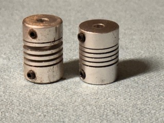
The YZ min lead screw connector is “sprung” from working against the resistance. There was tension and an audible noise when I released the grub screws on the min side. The screw is also caked with the grease/sawdust material. Here’s a picture of my min and max connectors once they were removed:
This explains a lot of strange behavior I had seen as I tried to finish the gift projects. Very inconsistent Z-height was the most common problem. Unfortunately it caused very inconsistent inlay plugs, and required quite a bit of rehab work on the final pieces. (Still wasn’t happy with them.)
Based on these findings, my action list for the LR4:
Improved Dust Collection.
Replace Z-connectors, YZ rails
Increase size of Z endstop wires
Maintenance schedule - I need to inspect, clean and lubricate the rails, screws and other motion components on a regular schedule.
I also think I could do some of the work out in the middle of the table. I think the sawdust problem comes from only being 30" wide and “planing” the tops of wood workpieces. The larger bits I use for that task generate larger wood chips at a much greater volume than other operations. For rigidity/stability I had tried to keep it close to the min side. But I think moving the work more to the center would probably decrease the sawdust piling up on the rails and motion system.
After a few hours of progress, I’ve assembled the beam, YZ plates and core. I’ll need to add some spacers on my table to ensure good running surfaces.
I’ll obviously have a better feel for rigidity/performance compared to LR3 after I’m able to use it, I did want to record some thoughts about assembly.
Positives
I love the cable management. The wires feel protected and tidy. Definitely a positive.
I like the z-screw assemblies.
I like the endstop placements.
Assembly notes:
Some of the wire management channels are tight. I did use a variety of tricks to fish the wires through. Note that this is one place to read the directions through, then come back and go step by step. I did find it easier to fish some wires in a different order.
I think PET-CF likely makes fishing wires through the tunnels more difficult. The rough texture seems to make it drag on the connectors, leading them to be more easily stuck. Softening the leading corners on the connectors may help. Also, thinner layer height for some areas may lead to a smoother tunnel. Not a huge deal, but was my impression.
Used a deburring tool to eliminate elephant’s foot where the braces hold the rails.
End braces are ~20g heavier than others.
Removing connectors did not work in any of the tight situations. There is room for the connector to pass, and it is worth leaving it on and just figuring it out. It did help to have slack in other wires so I could pull as a group through tight areas. Advice to future self if re-assembling, don’t pull wires fully through until all wires are in place for a given tunnel, the slack can be helpful.
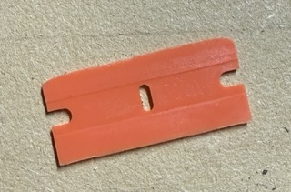
I use these orange plastic razor blades to remove prints from my build surface. I clipped one off and sanded it smooth to create a great little tool for jamming the wires in to place on the bottom of the YZ plates.
Overall, I really enjoyed this part of the build. (And yes, I watched Silo during this portion and the post name is an homage.)
Build is going pretty well. I blew up my ESP32 running WLED. Turns out the buck converter was just passing Vin through (I got distracted and thought I checked when I didn’t ). It’s all in the trash, the perpetrator has been flogged, and repairs are underway.
I did come up with a question for those running spindles on an LR4. How have you positioned it, or modified the dust shoe, so that you can get access for bit changes? I can barely squeak my wrench in to secure the spindle without the collet nut. Just curious what others are doing.
I also realized I don’t have any real way to measure my spindle speed. Since it seems that the speeds and feeds are so job-specific anyway, is there a problem if I don’t have this information?
If your vfd supports Rs485 just get that module and use it on your jackpot. In the override section of the webui you can control/modify it or by moving the controls on the vfd you can/ just convert the rpms
Build Log Entry #3: Electrical, Spindle, and Initial Squaring
I finished up the electrical and I just couldn’t help customizing the extension cables a bit. I fitted the panels on the back, but I need to customize those a bit too (Especially the panel over my Jackpot.) For the cosmetic-only parts I used a Matte Black PLA which used CF to create the appearance. It’s pretty brittle and I’ve broken several parts if there is the slightest bit of stress. Overture Matte Black PLA. Looks really cool but I don’t think I’ll be using it again for any machines.
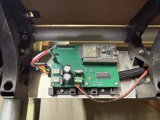
My EE student son has been working hard on a PCB based on the WLED controller I’ve been breadboarding. I think I’ll probably install one when they arrive to take care of the lighting.
The RS485 stuff took me a while. Fluidterm was invaluable in figuring it out. Turns out some of the sample code and images reverse gpio13 and gpio15. I ended up setting them according to BDring’s board rather than any of the references. The VFD is an H100, so most of the defaults work, but it takes a bit to go through and set them all up. Baud rate, etc. is some of the last, but most important. As pointed out, it gives me a speed, however, I don’t really have any way to know if it’s true. Not sure it matters enough.
I had to pull and reattach the struts/rails to shim them out about 22mm. And it appears I shifted the rail side about 6mm. When squaring I ended up compensating with pullback. I’ve got the room to spare, and I don’t really want to extend the screw that far. If it causes problems I’ll revisit.
Struts are temporary, I need to modify the bottom strut to have holes for mounting my hardware.
I have aluminum for the permanent struts. But I think I’ll cut another set from something more forgiving before committing to the metal.
I want to create a new spoilboard. I cheaped out on the last one at 12mm. I want to create an 18mm spoilboard with mount points for fixtures and jigs.
I need to figure out how to get a wrench on the spindle when I change tools. The current (Makita) shoe doesn’t allow for any of my wrenches to fix the spindle while I change bits.
Kinematic mount needs Laser, Mist Coolant, and Pen/Dragknife tool mounts.
Because the existing dust shoe design for my Makita encircles the router in the area where the top wrench would go for a 2-wrench approach (which is what I prefer), I got an idea from someone on here (and forgive me whoever you are for not remembering for certain but it may have been @Jonathjon) in which they used the dust shoe for the Dewalt because it does not have much protruding from its flat top, and it allowed raising the shoe enough to get a wrench in. So, I did a teensey remix of the shoe for the Dewalt, to create a shoe for my Makita router that rides higher, and encircles the router just above the area for the top wrench. It’s been working well for me.
My son’s WLED controller (his first PCB design) running “Musings”
However the big point of this post is that I had one of those “don’t leave your machine unattended moments” this weekend, and I was right there to kill the machine before a fire started. I love the LR4, and I’m simply noting how it happened and what I did to temporarily fix it. I’ll be looking at more permanent measures when I replace the temporary struts.
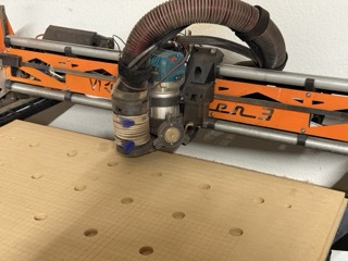
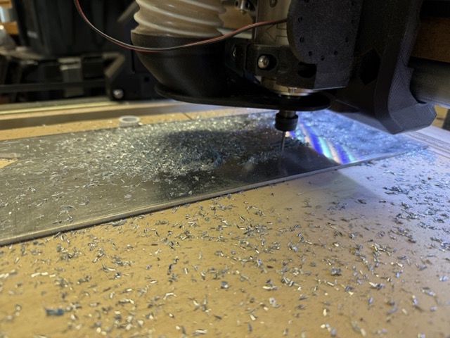
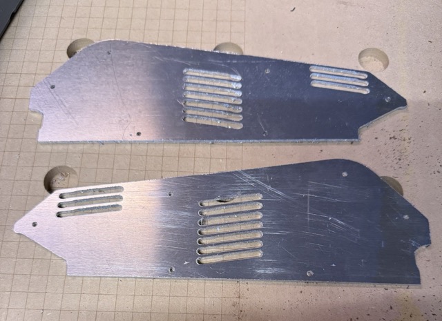
I was doing my first aluminum cutting this weekend. I needed to work out feeds and speeds (and z-flatness), so I decided to start by cutting some Peter Plate covers out of some scrap I can buy by the pound. During the cutting of the second part, the machine suddenly dropped, lost connectivity and was DOA. Unfortunately, in my temporary setup, the spindle is not yet hooked through the E-stop, so I had to kill both quickly. No fire - whew.
What happened? Well, initially in the aftermath I could not talk to the ESP32 at all while it was on the Jackpot. But when I removed it everything appeared normal. I was describing my frustration with my son when he said “it sounds like something is shorted on the Jackpot.” Then we walked into the garage and he said, "Oh, I bet you had an aluminum chip land on the Jackpot and short something. (Then he turned around and went back in the house .)
I used some canned air and carefully cleaned the Jackpot off, then tried again and sure enough it worked! The gap (necessary) between the bottom strut and the bottom rail had allowed aluminum up to the control board area. I have Doug’s panels installed, but I need to figure out a solution to the Jackpot bracket to better protect it from the debris generated at the cutting area.
Moral of the story - don’t leave the machine unattended.
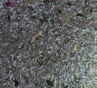
Chip size at 15000 rpm and 5mm/s with 5% finishing pass on a 1/8 end mill. (Not trochoidal.) I’m still not happy with the cut quality and finish, but it’s my first attempt. The parts are useable but not cosmetically acceptable yet. I could try trochoidal milling still. (Note there are also some marks from an attempted chamfer to give it a more finished look. I think I’d need to flatten the spoilboard to have it look good. I also changed the tool definition a bit which helped a little.)
I’ve been running the machine with hardboard struts. I’d really like to get it closer to final form so I can move it back against a wall and finalize the dust collection. However, it’s easier to work on it if I can move all the way around, so it’s sitting in the middle of the garage until assembly and final squaring.
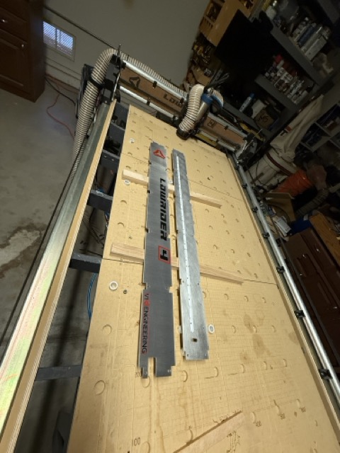
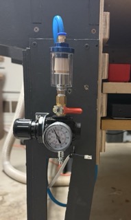
I’m happy with the Aluminum struts I cut last weekend. I added a coolant system to the machine, and learned quite a bit about cutting metal.
I use isopropyl alcohol for the coolant. Amazon.com
I still need to find a holder for the bottle while the machine is working. But I have a shop vac full of large aluminum chips. (I just vacuumed it after, I don’t collect when cutting with metal.)
I was hoping to mark the aluminum with the laser, but the marking spray had fallen and the nozzle is shot. So I pivoted to a mask and paint strategy. Not perfect. Despite multiple passes the laser failed to cleanly cut the corners of the mask material. I suspect the laser intensity at the corners varied as it accelerated “out” of the corner. The larger letters were fine, but the smaller letters were pretty rough. Good enough for a machine strut, but I need to work on the settings.
Very happy with the LR4 so far. I’m really looking forward to projects!