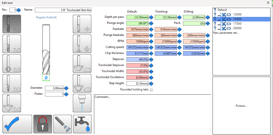
Here are the Trochoidal settings that I used. I was able to cut 9.5mm aluminum in a single pass with these settings, although I was using an IPA mist system (which is very helpful with Aluminum cutting)
You’re cutting REALLY close to the hold down screw, is it possible that you brushed against it and skipped a step there? Aluminum can gum up an end mill really quickly, especially if you aren’t using IPA mist cooling, or if chip evacuation isn’t really good (re-cutting). You may need to check your end mills frequently, and change them at the first sign of dullness or aluminum welding to the cutting surface.
Yea, I should have rigged up a mist system for the cuts, I was using IPA in a spray bottle, but it was not consistant, and I did get some gumming up. I tried playing with feeds/speeds a bit, and got nice chips, but I also noticed much better surface finish with some IPA.
I will need to go back out to the garage and see what the trachoidal settings were that I used, tried a few settings I saw from the forums and others on youtube with LR3/LR4s. Thanks for you settings though, I do want to play more! I did notice a big difference in bits though, I usually use SPE, which work well on my smaller, more rigid machine, but also tried some no-name ones from amazon with a coating and they were way worse. got gooey in maybe 1/5 the time of the SPE bits.
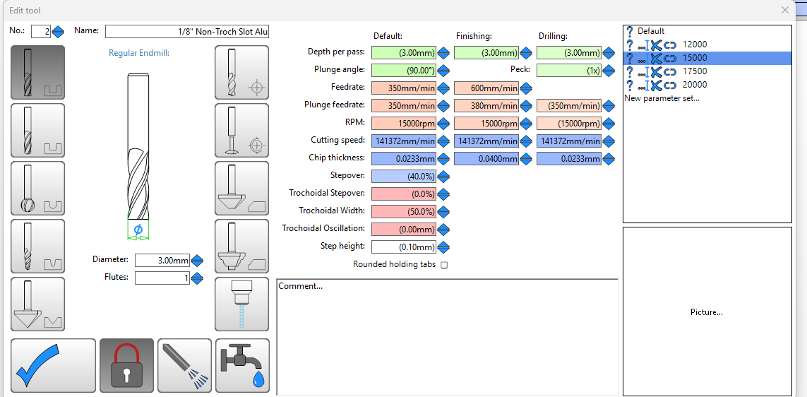
My non-trochoidal settings are pretty close to yours, but I was doing shallower DOCs of only .6, but I think my feedrate was 480 with the same RPM.
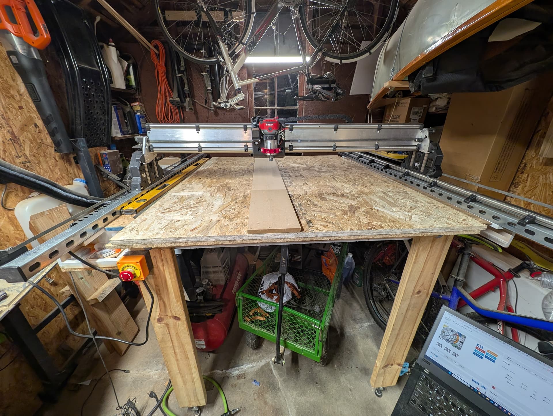
I decided to go stout and heavy (I got a great deal on stainless tubeing and like the look). I did swap out the z screws to finer thread to deal with the extra weight though…
yea, I was REALLY close to those hold down screws, but I never touched them. Most (maybe all?) of my missed steps where when I went from low load to high going into one of the ‘slots’ of the strut. I am using a Bauer (makita close) router, and when going from maybe .2mm doc on the side of to full slot, the router bogs very briefly, then adjusts, but I think transitions are where I had the issues.
Yes, made temp struts out of PET-CF like all the other printed parts! My gut is the bit breakage is related the big 29” gantry having a bit of flex in it due to its size. I may also need to go a a little tighter on the belts too. Everything IS working, I think I need to tune it a bit, and then figure out what the limits of the machine are. But from looking at what some other people have been able to get, feels like I still have a few tweaks on my side. I didn’t want to go down that rabbit hole until I got proper struts made though!
And assembled. I still want to recheck square and tram, but with the big plates she is VERY rigid now! Thanks for the suggestions, now to see if any of those unexplained issues I was seeing go away!
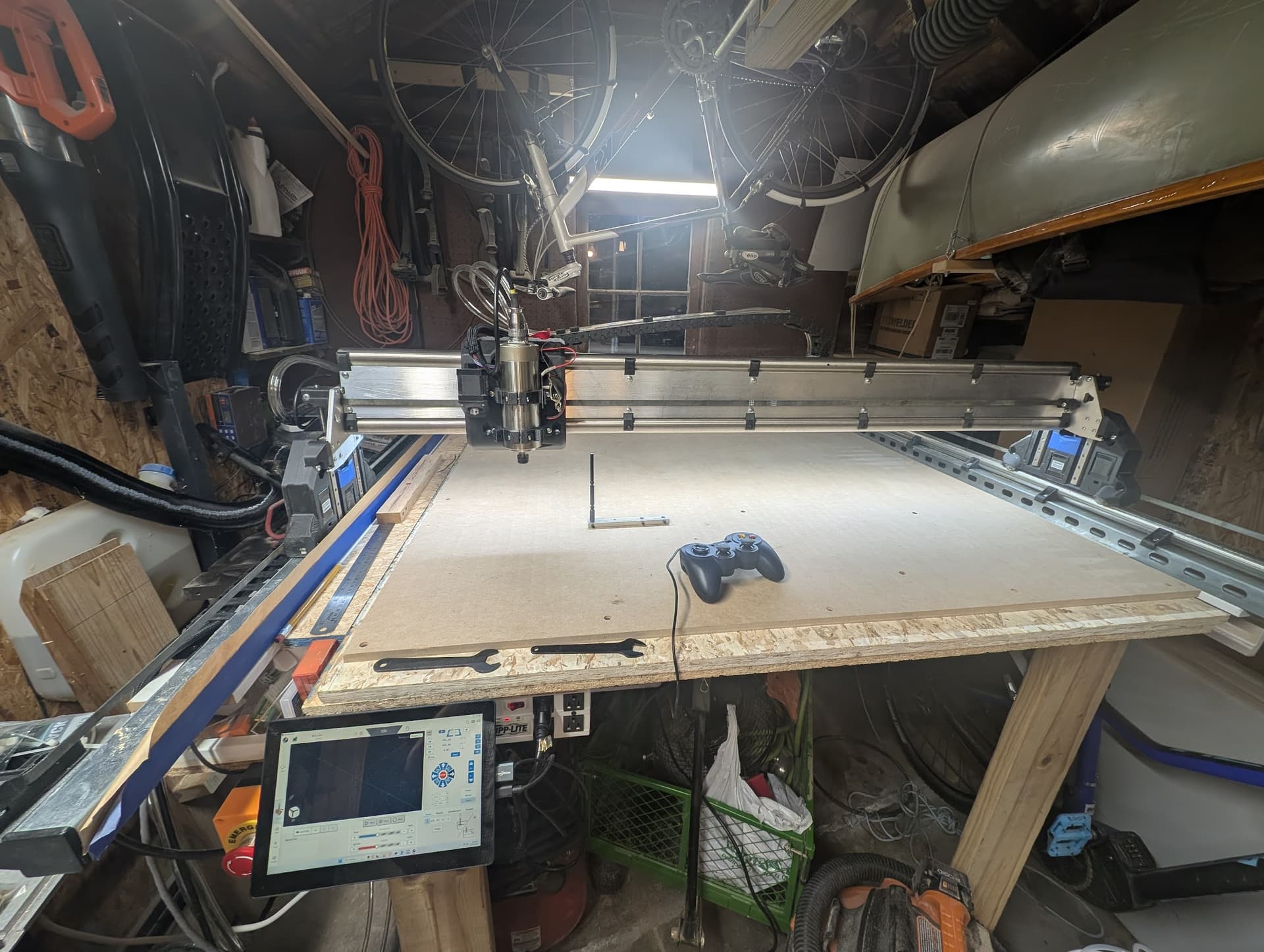
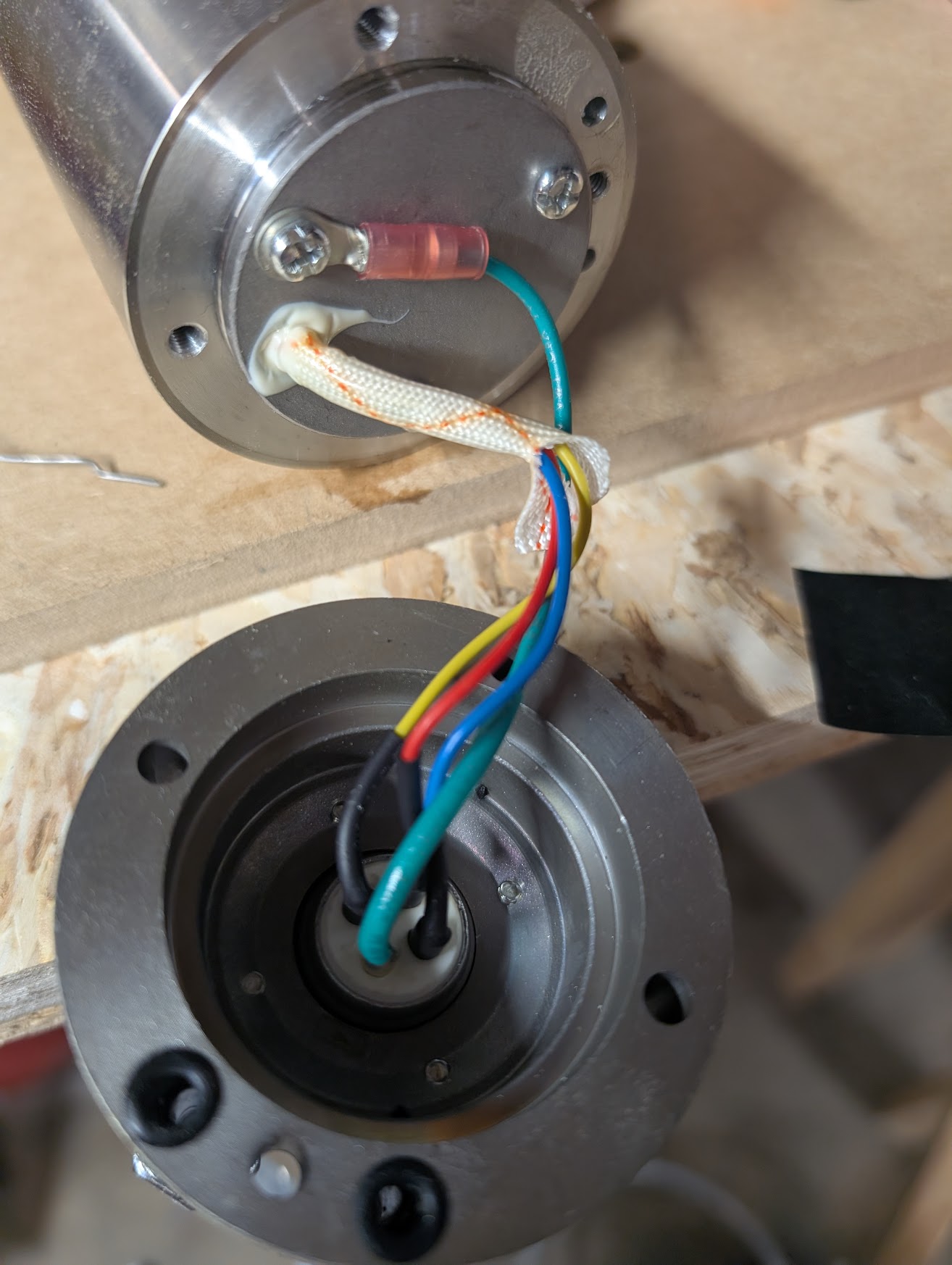
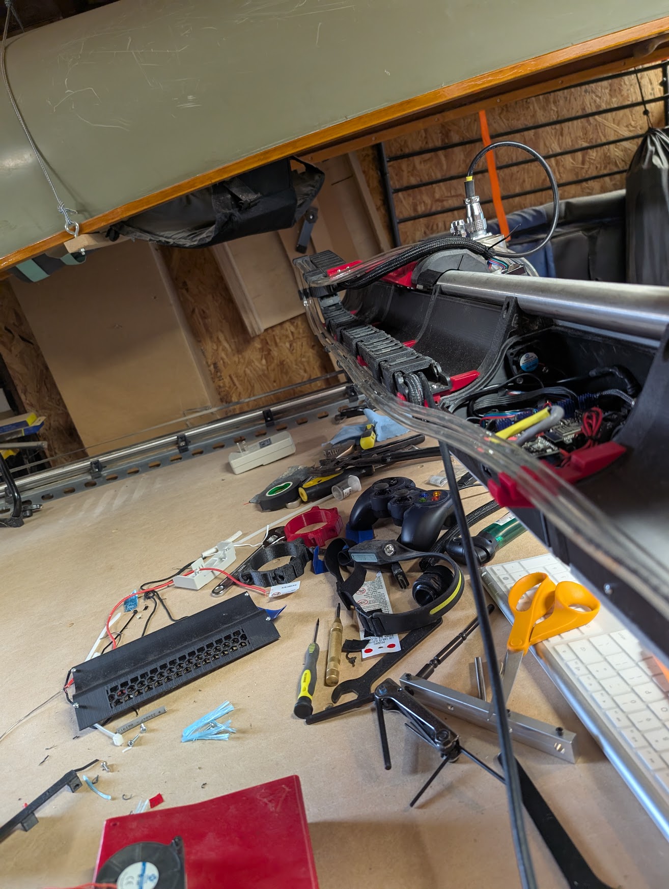
Now with a water cooled spindle, 24V gantry lighting and a dedicated touchscreen computer for control. Also using the RS485 adapter on the jackpot to control the VFD. Just need new fittings for the coolant lines as I am using better tubing, but it was not compatible with the fittings on the spindle!
800W Water cooled spindle. Note, many/most? of these do NOT have the internal chassis ground connected, so had to open up and fix that. Once that is done, the spindle is great. I don’t have a picture, but the compression fittings on the spindle wouldn’t fit the thicker tube, so had to special order some M8x1 hose fittings to install.
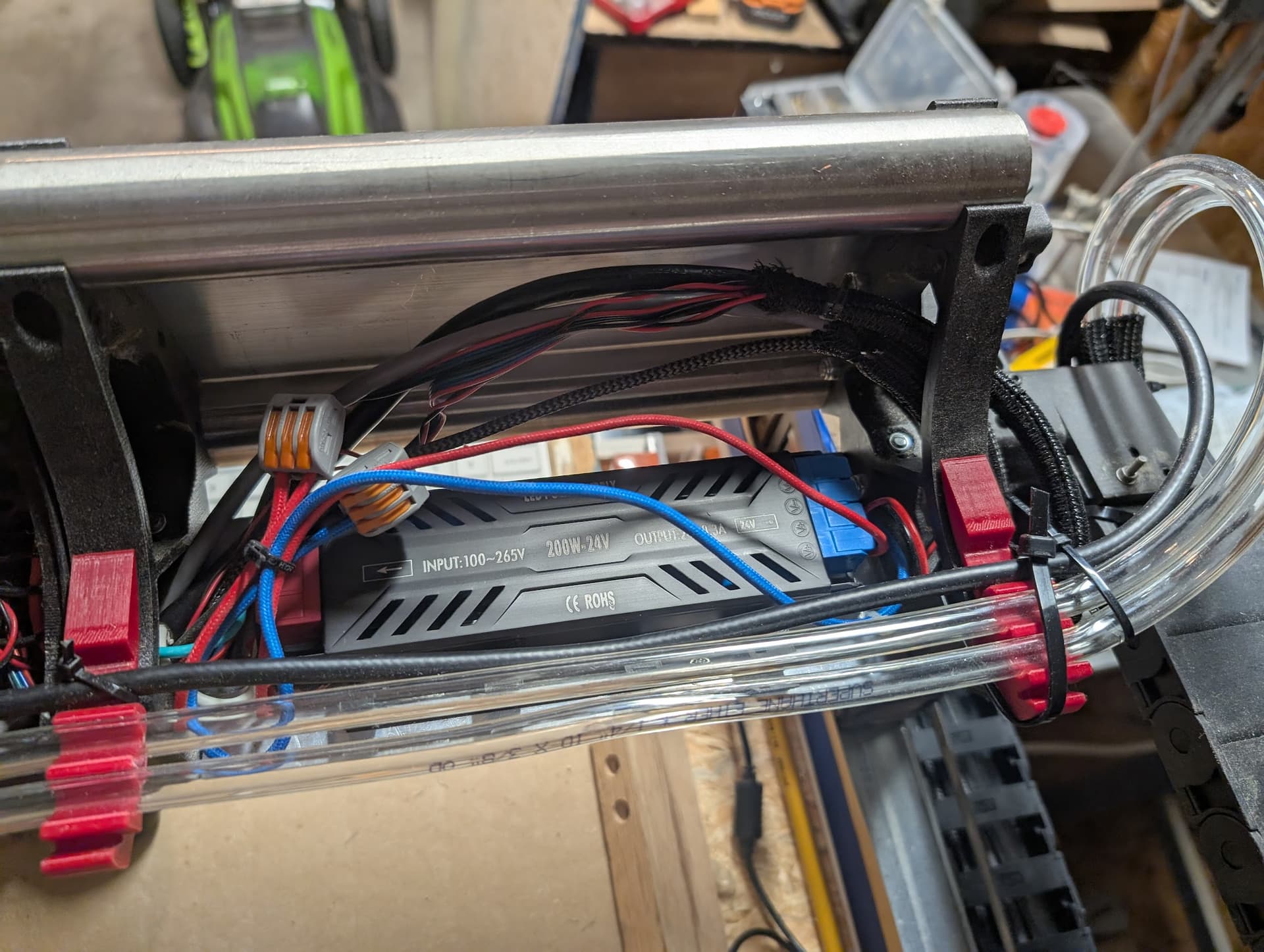
fixed mount 24V power supply with extra power for more fans, LED lights and future maybe a laser in the future. You can also see a couple us custom tube clips I made but combing the X Drag chain rest and added half of a drag chain tube clip. Using the regular clips on the X Drag chain, but again had to modify clips for my slightly larger coolant lines. the factory silicon ones are 8MM OD, but the more kink resistant tubing I am using is slightly thicker and has a 9.5MM OD.
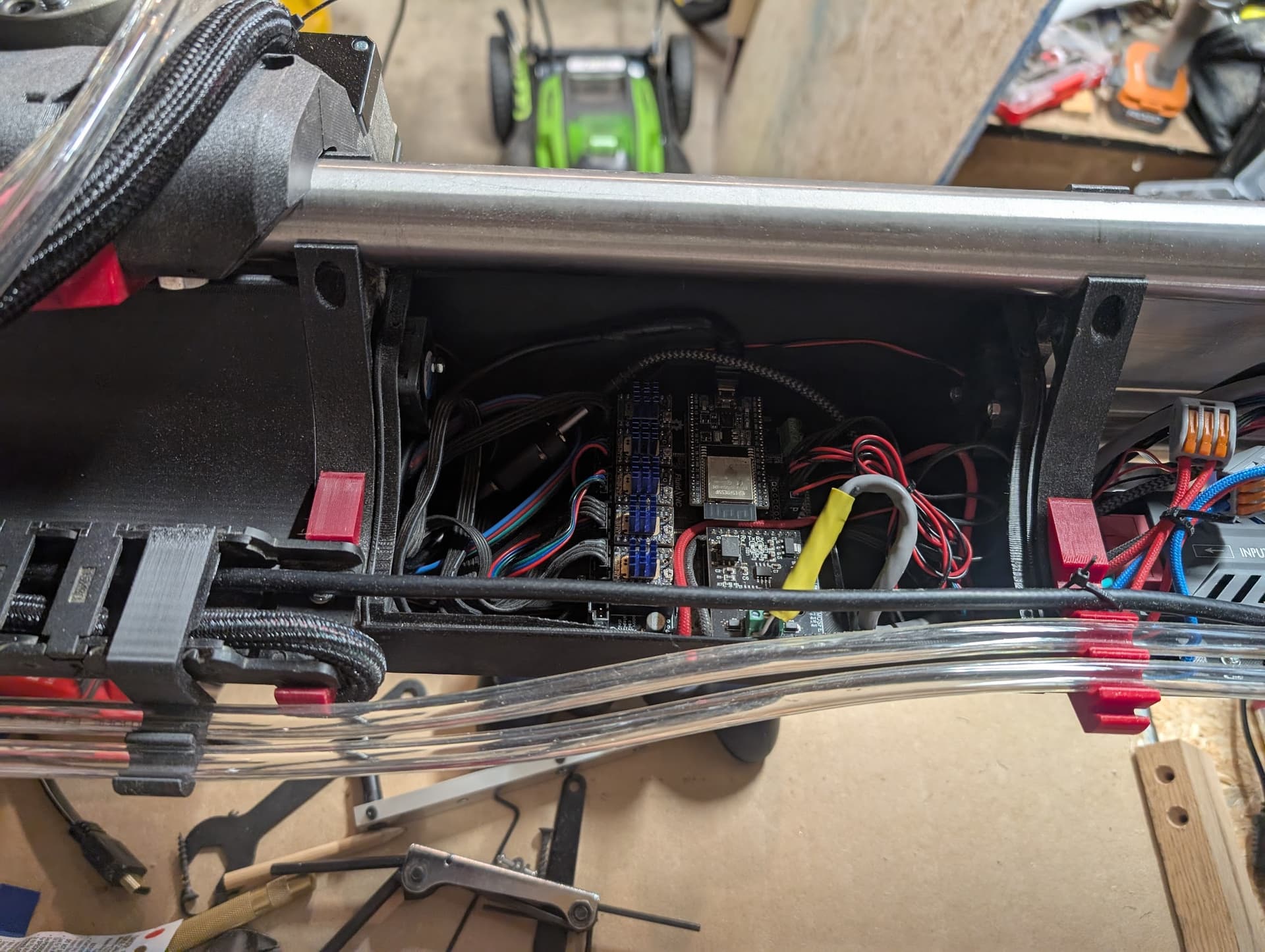
The jackpot with the RS485 IO board from Bart. Hard to see, but to high flow fans in push pull through the Jackpot section to keep the stepper controllers cool…
I also have a tool setter I need to install and wire up to help speed up tool changes using the last gpio left on the jackpot. Then I should be set to start building things!