Thanks for all details into the build-page i was able to order all parts easily
1 Like
Thanks for all details into the build-page i was able to order all parts easily on amazon-de
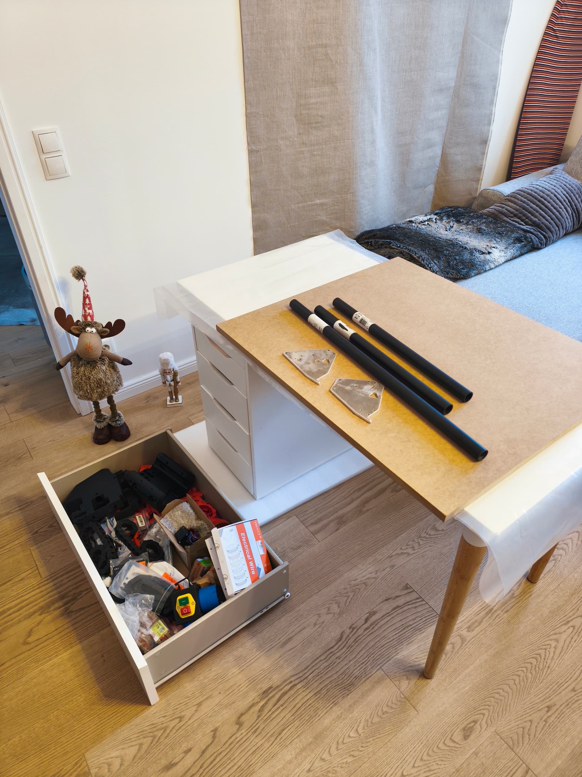
the black rails i bought 27.5 mm from hardware shop OBI.at in Vienna. I had to print small ring-adapters 27.5-29.5mm
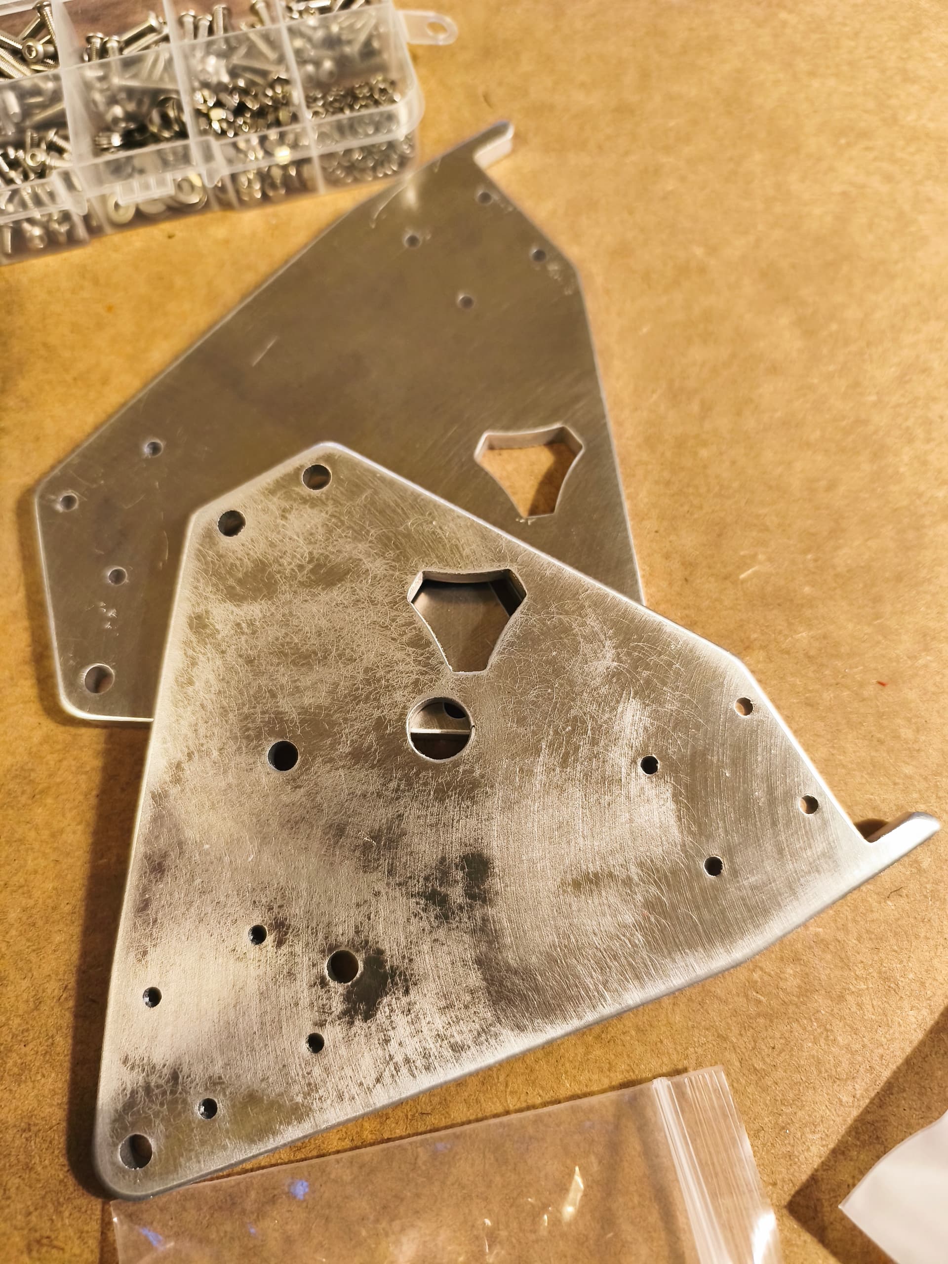
- ordered the metal plates directly from philipp @ hawiwe-de. Philipp was very fast to make them ready, was shipped to me from Germany in 2 days! overall cost 38 euro + 7 euro delivery.
- ordered board from elecrow-com. cost 45 euro + 6.94 euro delivery. I have decided to take cheapest delivery (from China to Vienna). i was expecting to deal myself with customs. By surprise there was no need - the package just arrived to my home in exactly 11 days from the order was placed
Yes, Elecrow ships Delivered Duty Paid (DDP).
Ah, they arrived then. ![]() Glad they did. Looking forward to seeing your build threat! Bonus points for putting up one of my stickers somewhere in the Prater.
Glad they did. Looking forward to seeing your build threat! Bonus points for putting up one of my stickers somewhere in the Prater. ![]()
1 Like
thanks to Philipp, first delivery was lost but he cutted me the second set just at cost of delivery costs. i can only advice his work for alu parts. nice cuts
5 Likes
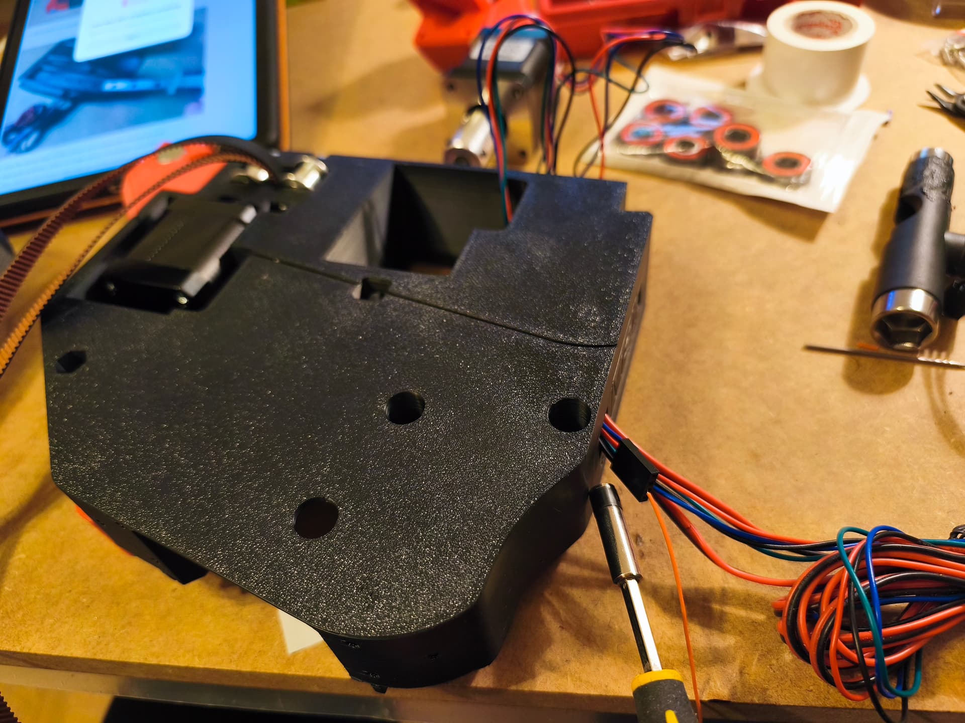
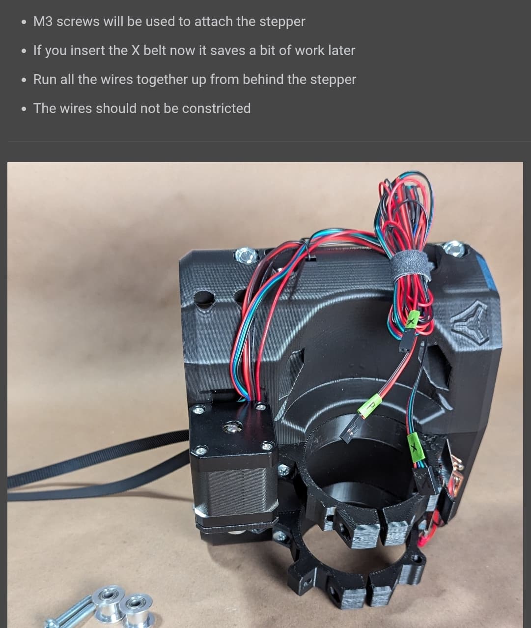
suggestion on Z drive mount.
the hole is too small to push additional Z cable into tiny slot where Y0 cables already in.
solutions:
-i had to solder small cable to stepper header to pull it through
-please consider to improve 3d model
You can get them though without soldering that. Sometimes it takes patience, wiggling the wires just right and holding your mouth in the exact right spot. But I promise its very doable. For me its easier to put the Z wires in first, then the Y motor wire, then both endstop wires.
2 Likes
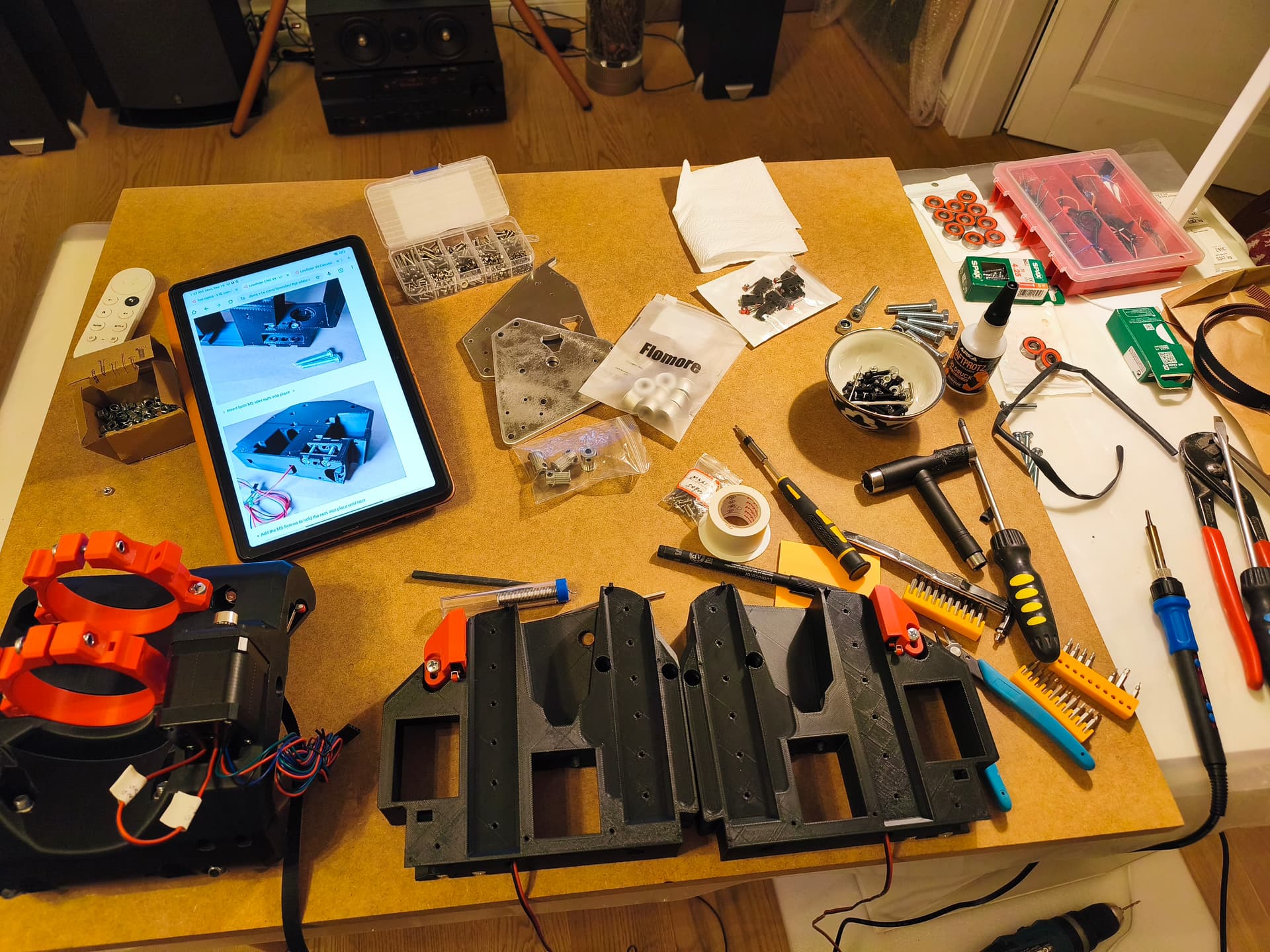
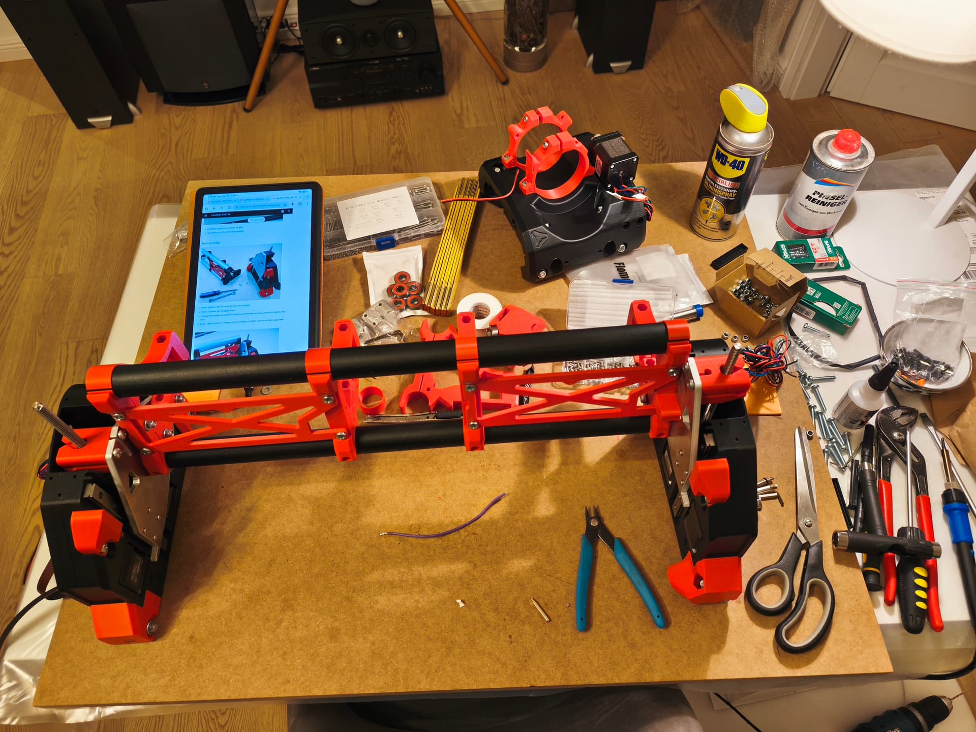
building the Y axis… easy work with the online doc (no need for phD ![]() )
)
p.s. (last picture) most extreme rail holders could be adapted for nut slots… strange those are not done and i have to hold it
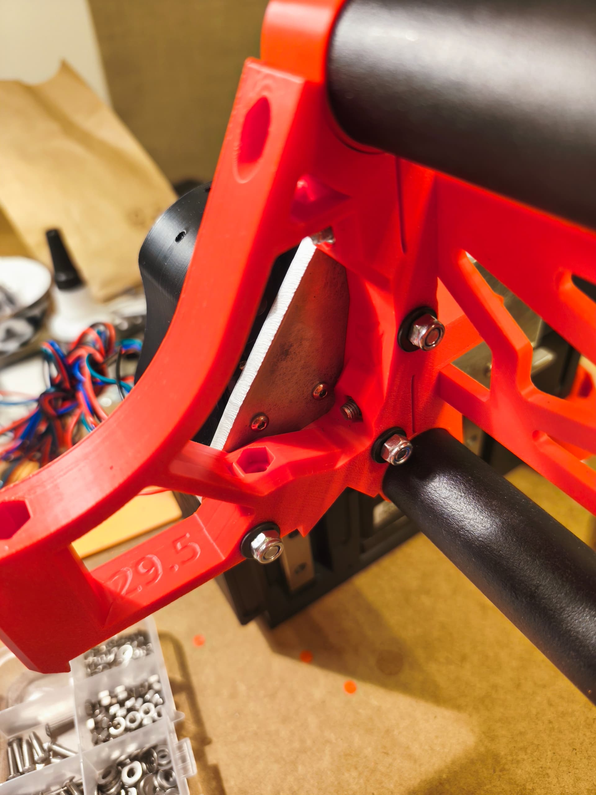
This was talked about a lot in the beta and it would cause the shipping of printed parts kits to get a lot more expensive to add that and make the braces wider. As it is now it takes every bit of available space in a box for Ryan to ship them. Its not that big of a deal to hold 6 nuts and tighten them ![]()
2 Likes
Especially if you did the LR3 and had to hold 80 nuts or so… ![]()
1 Like
That’s for sure!
1 Like
so it seams to be more a legacy issue. understand. lets me finish building different device and i willbbe happy to return to LR community enchanced 3d models
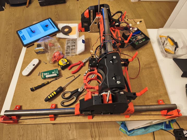
Finally completed the mechanical build. Took a while to get proper 30mm rods.
Now facing major obstacle to find out why at the core there is only 1 end-switch for X, but on software page there are two connectors X0 and X1 required.
In fact, in core part there is place for second end-switch but no instructions whatsoever about it.
Where should I connect the first switch? To X0 or X1 outlet on the board? (I bought jackboard v1 from escrow)
The x minimum is where you put it. And you only need one for x. The x max side is a limited use case for an advanced configuration most will not need, so ignore it.
2 Likes
Hmm, I only added a note to the sideplates. I proposed a change for the instructions to include it as well for the core.
You’ve got a mail btw. The plates were at your post office and were sent back because they weren’t collected. ![]()
1 Like
Here are my very important last steps that can be very usefull for HOW-TO pages.
WARNING: follow next steps to avoid destroy your LR4 during first motor runs
-
BEFORE you try to move axis motors, important to verify that all end-switches are working fine
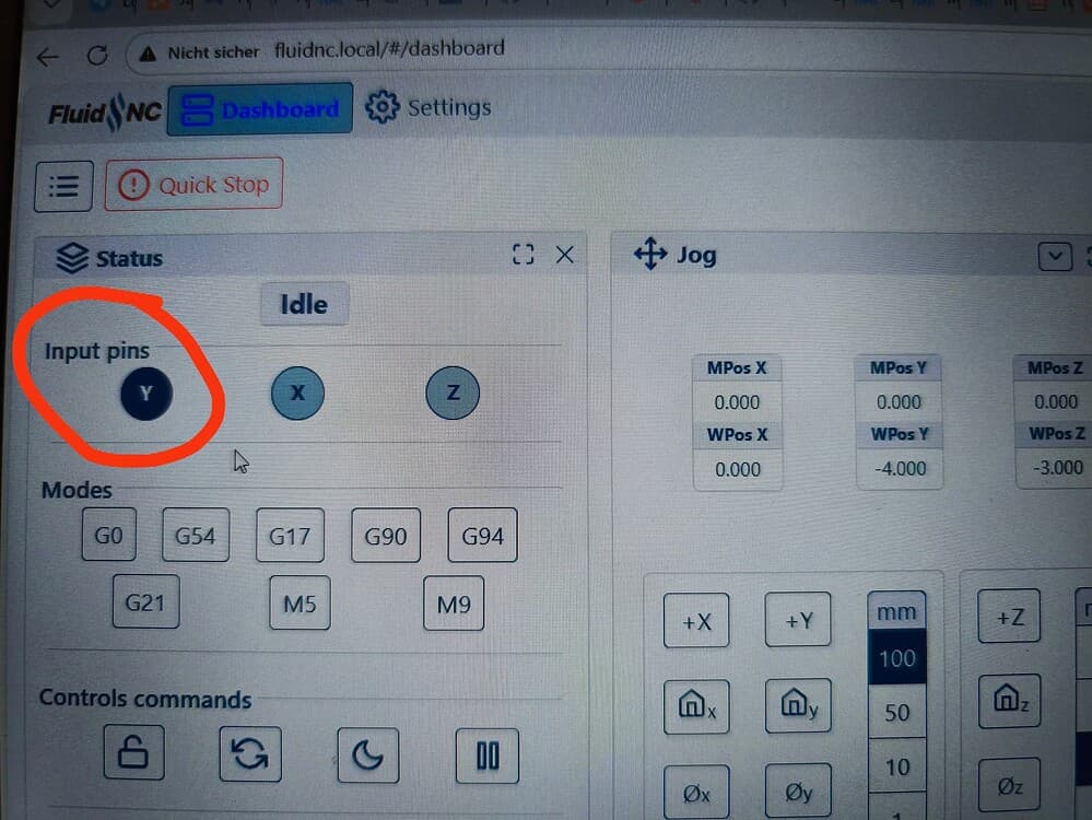
open FluidNC and see the main page.
put into terminal command line
$MD
(it disables all motors)
$ME
(it enables all motors back)
toggle manually each end-sensor (single X, two Y, two Z)
each time you touch end-switch the Status display must change color of the respective X,Y,Z signs (see picture)
carefull: dark color means one of end-switched is toggled.
Notes: that helps to verify that all 5 end-switches works correctly and Home-sequence will working -
VERY IMPORTANT to verify that motor connectors connected right (and not inverted)
home sequence: most important problem is polarity of motors… ehen homing pressed, motors suppose to:
position core in the middle of your table
plug power on
open FluidNC.
enable motors (see howto above)
select JOG button “10” for “X,Y move”
click button X-
CORE must move into direction TO the X end-switch (if not, power off, reconnect board motor connector 180 degree)
click button Y-
CORE must move into direction TO the Y end-switch (if not, power off, reconnect board motor connector 180 degree)
click button Z+
CORE must move UP (if not, power off, reconnect board motor connector 180 degree)
if movements are in opposite direction it will be big trouble during your first home-sequence.