I’m Gigi, from Italy. I’ve made upgrade from LR2 to LR3.
I’ve a little issue and I cannot understand whats the problem.
I’ve a little difference of height from the surface of the table along the X. about 2 mm from extreme left to extreme right.
I’ve made the squaring of the LR3 succesful, but I can’t do the calibration of Z-axis.
I’ve followed the instructions on the site.
I’ve noted something strange. When homed all the axis, X and Y show 0, while Z-axis show 200.
When I send the command G38.2 Z0 using the probe, the Z axis decrease the value … till about 130.
I have a difference from extreme left to extreme right of about 2.5 mm. I try to give the command M666 ZXXX with the difference. IF I give positive number the difference increase on the same side, the other side remain the same. I’ve tried to give negative number but when I send the G28 Z0 one of the two Z motor reach the stop before and start to make noise.
I don’t know how calibrate the two sides with the same value.
First of all, 2,5mm difference between Z1 and Z2 seems (too) much. After my final assembly, I had a difference of 0,34mm (my X-rails being 1200mm). So I would start with checking the build, especially the Z endstop positions (are they different? Different switches? Or maybe bent?) Is your table levelled?
The second thing I noticed in your description is the problem with the homing process for Z and the noise. Are u using the SKR Pro 1.2 board? If so, can it be that your Z endstop does not register? There is an issue with some SKR Pro boards where triggered endstops are not being read by the processor. And a workaround for that (assuming that the cabling of your Z endstops is correct).
Nothing more to say from here, hope this helps.
Best, Christian
P.S.: A homed Z shows 200, that is normal with the pre-configured firmware. As is the decrease when moving down to 130 or 120 where the delta 200mm - 120mm equals roughly the maximum height a LR3 can operate.
I just finished building my LR3 and had a similar problem. Which Z drive is making the noise? I had a problem on the right side, the X max side. The problem was that too much of the X belt extended out the side of the XZ stub as shown here:
Ryan does note that you need to be sure that only a small loop extends past the edge of the right surface of the stub mounted to the XZ plate. I missed that on my first reading.
The other problem I kept having was that the end stop wiring kept coming disconnected every time I put the control board cover on. I eventually removed all the connector shrouds and now they stay connected much better.
I became very familiar with e M119 command (end stop status command).
Thank u for the reply. It’s strange also for me the difference of height. I’ll recheck all the Building steps in the next days.
About the endstops, I think they are working well, because with the command g28 z0 they go normally till the endstops (with m666 z0). I have the noise problem when i set a negative value with the m666 command.
Now i Would like to know how use the m666 command to level the Z axis. When I set m666 with positive value It change only the side of the X0 (raise up) and the Z near Xmax remain the same. How can i change the Z at XMax???
I’ve checked the structure and seem to be good.
So i’ve tried the Z leveling again, succesfully. I don’t know why but today using command m666 with negative value I have changed the height of Z at XMax. I don’t understand why Yesterday with the same procedure no changed on that side.
Boh
Now I’ve the Z level with same values on both sides.
In the next days I Will unmount and remount all the parts to check the structure.
I Will send you updates …
Bye
Gigi
I have about a 1.6mm difference between the 2, so I get it.
First, the Z stops are physically adjustable, so do as much of that as you can.
I didnt have much luck figuring out the M666 with negative offset, so my machine is now a little weird with Z1 now on the opposite side of Y1. (Then I changed out the board to something else entirely, but it’s still that way.)
You can swap the Z1 and Z2 axes, just be sure to also swap the endstops. With the board powered down, just switch the plugs to Z1 with Z2 for both motors and endstops, and you can use the positive offset. It’s a bit of a kludge, but works fine, and in operation, your machine will not care in the slightest which is 1 and which is 2, as it moves them from homing in lockstep.
thank you for your reply, but I’ve solved with the command M666, without swapping the motors/endstop.
If you use M666 with negative values you change the distance of Z1 in my setup, Z1 is the motor at Xmax.
with the command now I’ve a differenze under 0.1mm between the two z motors.
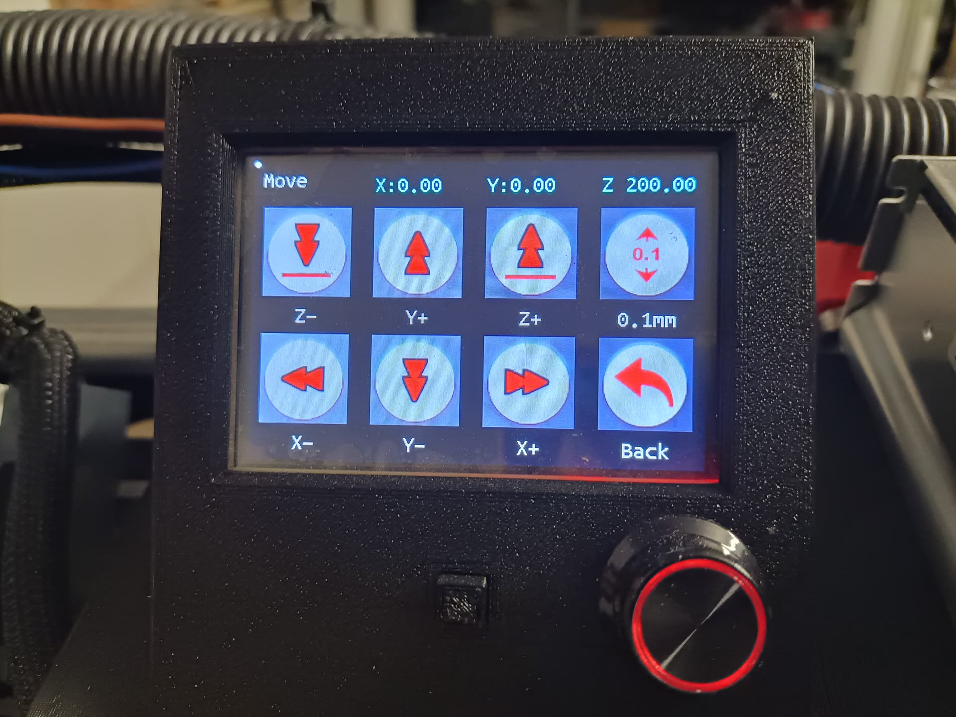
I’ve just reached the point where I’m encountering the exact same problem. Z=200 when I start. I’m bumbling around the LCD interface looking for a way to zero the Z with no luck. It sounds like you entered a command to do this. Where do you enter the command M666? Is that what’s needed? So sorry but I’ve never had any exposure to this and when I followed Ryan’s instructions to print the crown, the machine just tries to lower and I get a horrible grinding noise from the Z motors.
Are there any instructions on how to use the LCD interface for the Marlin board? I figured out how to move the gantry but that’s as far as I’ve been able to get.
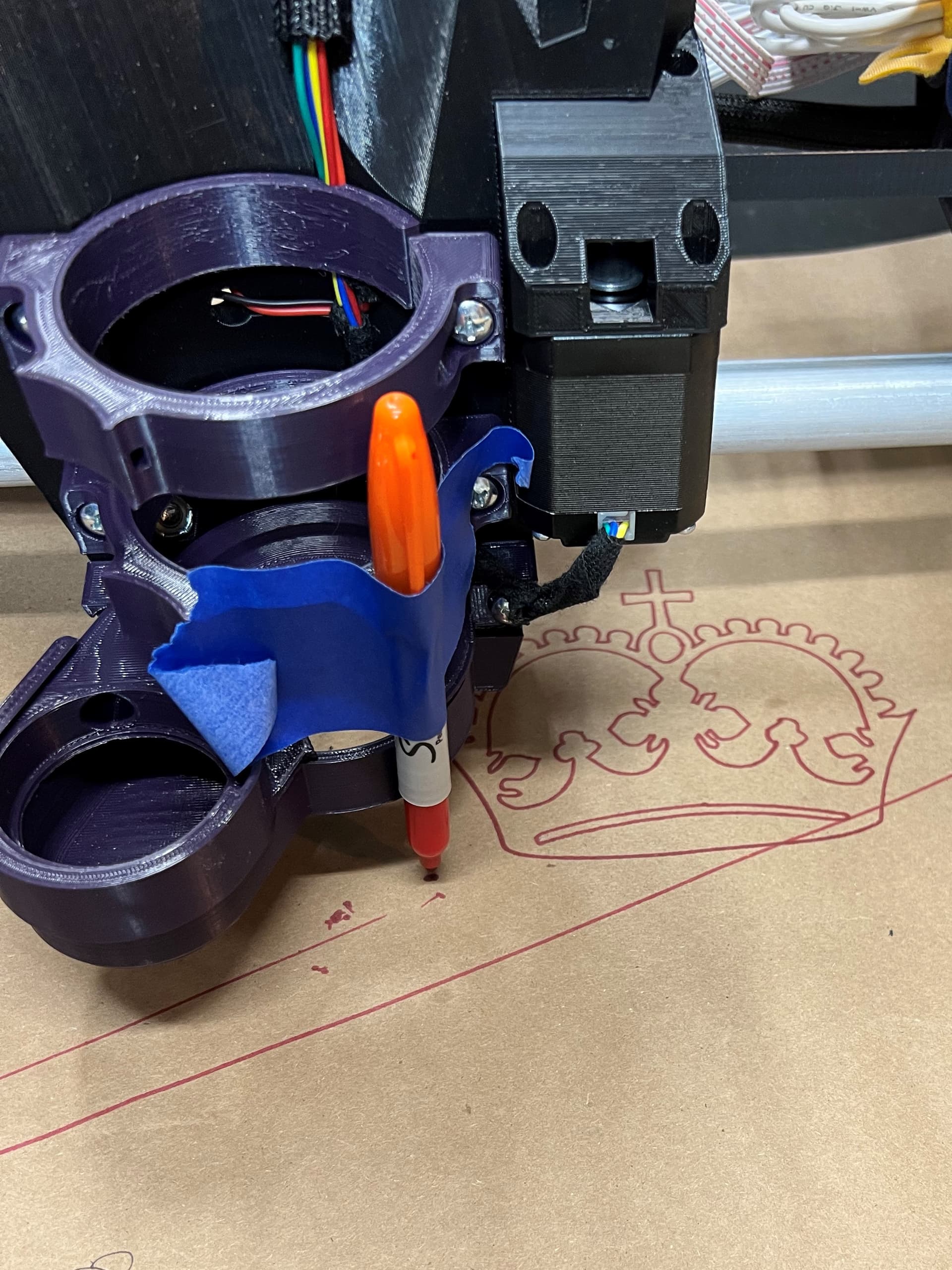
Thank you for the ready-to-go test file detail! I misunderstood the instructions, but now I understand the gcode to zero wherever the LR3 is positioned when it receives that command. And… I drew my first crown!
Now on to squareness test - if I can manage to keep everything plugged into the board. Wire management is a bit harrowing at this stage.