Hello
I have not long finished building my LR3. I have built using SKR Pro 1.2 and when I home all seems to work fine. Movement through Repetier is all ok, the axis all move iin the right direction.
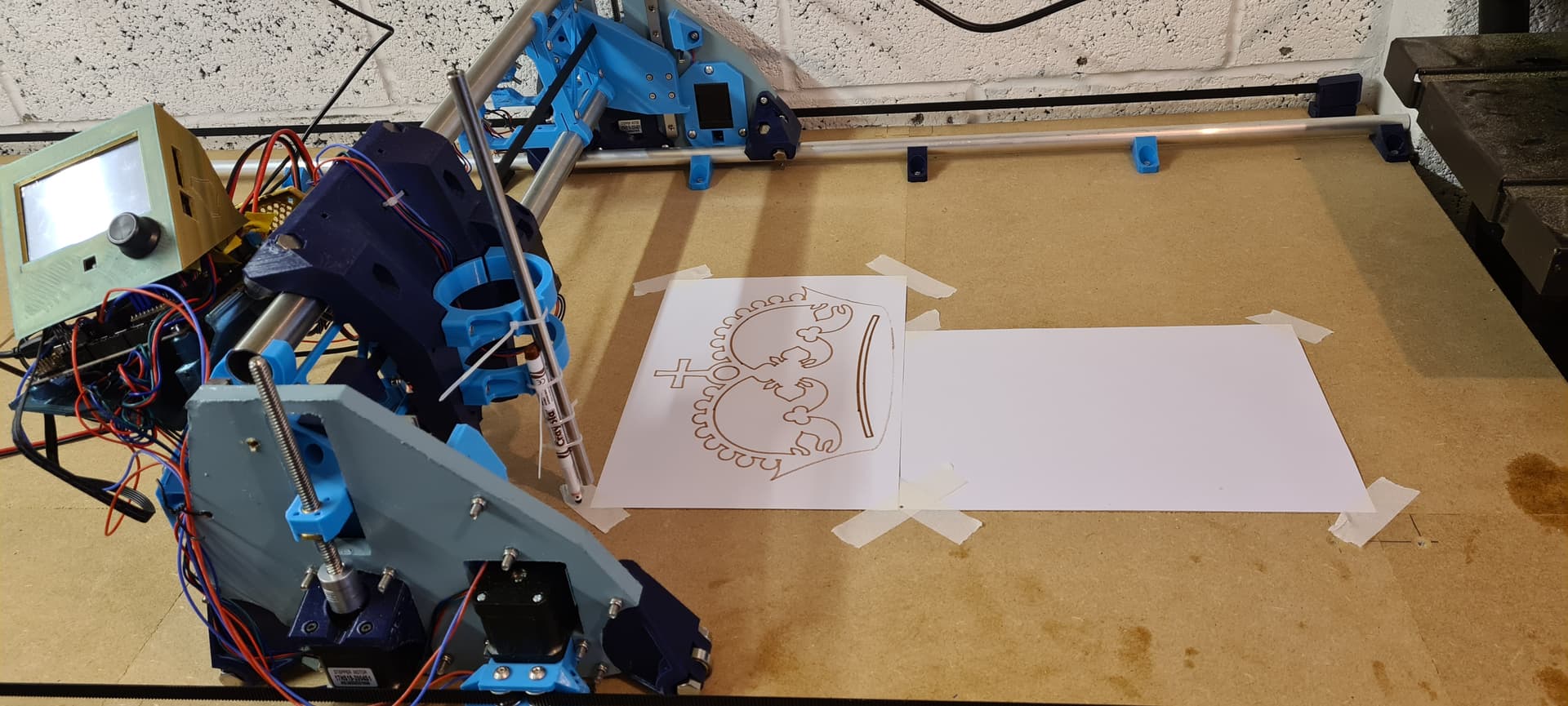
I have come to trying to complete the crown drawing but am having a few problems. My normal choice of software is CarveCo (peviousley used on a 3018 pro so i am familiar with creating toolpaths etc) and I generated code in that using their Marlin post processor. Strangely, although the LR worked and drew something, it did not resemble the crown, even though the picture displayed on Repetier looked correct. Unfortunately at the time of writing I dont have access to the machine so cant post a picture.
I decided to try and rule out the issue potentially being with Carveco so created the crown using Estl cam and set that up as described in the LR3 instructions. Again the picture of the toolpath in Repetier looks correct but when I now run the project the LR3 keeps driving the pen into the workpiece and the z axis wants to continue going so i have to hit the emergency stop.
Anyone have similar problems or know how to solve?
I’m not good with Gcode (i rely on software to do that bit ![]() ). Here is the top section from the Gcode created by Estlcam:
). Here is the top section from the Gcode created by Estlcam:
;Project Crown drawing for LR
;Created by Estlcam version 11 build 11.245
;Machining time about 00:04:02 hours
G90
M03 S24000
G00 X0.0000 Y0.0000 Z0.0000 F2100
G00 Z2.0000 F480
;No. 1: Engraving 6
G00 X102.6984 Y33.3595 F2100
G00 Z0.5000 F480
G01 Z0.0000 F180 S24000
G02 X103.6898 Y33.4897 Z-0.5000 I46.8245 J-352.7072 F180
G03 X102.6984 Y33.3595 Z-1.0000 I45.8331 J-352.8374 F180
G02 X144.2820 Y36.4155 I46.8245 J-352.7072 F900
G02 X189.3717 Y34.6108 I7.3948 J-379.4151 F900
G02 X221.4207 Y29.5599 I-27.0848 J-276.0630 F900
G02 X231.0109 Y27.1925 I-42.1516 J-191.3642 F900
G01 X229.7864 Y23.0448 F900
G03 X203.9594 Y28.3808 I-59.9336 J-224.9160 F900
G03 X164.8978 Y31.8655 I-49.5320 J-334.5614 F900
G03 X119.3347 Y30.7961 I-13.5991 J-391.7780 F900
G03 X85.9520 Y26.1413 I23.0062 J-287.0275 F900
G03 X72.8111 Y23.0448 I40.6993 J-202.1514 F900
G01 X71.5866 Y27.1925 F900
G02 X97.8441 Y32.6577 I61.1016 J-227.7519 F900
G01 X102.6984 Y33.3595 F900
G00 Z2.0000 F480