I am going to begin the upgrade! Summer is here and soccer coaching is on the wane until fall and I have some builds piling up! But I want to upgrade to the new LR3. I have a Carbide 3D spindle so I’m not sure which mount I should pick up. It’s 64.70mm diameter. I can’t locate a housing diameter for the DeWalt or Makita - so which should I order? Anyone with either (or both) can you please measure yours an reply with a detail? Or am I thinking too hard on this one?
I’ll keep this up as my upgrade log.
2 Likes
My Makita is 65mm. I think the DeWalt is 69mm?
I believe the Carbide Compact Router is a straight up copy of the Makita, body/head wise, so I’d go with the Makita toolholder.
1 Like
https://www.printables.com/model/360285-lr3-65mm-spindle-mount/files
I remixed this mount to use for my 65mm spindle. The Makita is the same 65mm. Remix Spindle Mount V2 is the one I run on my LR3 and its been great!

Ordered today! I placed the order with a Makita tool holder size. Ought to handle the Carbide 3D spindle. Can’t wait! But I will - but now I wish I asked for a quick delivery as I have a four day weekend next weekend - oh well, poor planning on my part constitutes no emergency on others!
I’ll be cutting my own XY plates with my LR2 - any thoughts on HDPE? 1/2" I’ve got a bit of it - anyone think it’s too flexible? Or how about plexiglass? I have a nice sheet of 1/2" of that too. I have access to 1/2" MDF or Baltic Birch. So I’m open to thoughts…
I was just having this conversation about the strut plates.
Acrylic/plexiglass is slightly higher young’s modulus than MDF, apparently and about 4-8x higher than HDPE.
From reading other threads in the forum, MDF is preferred to plywood, so I would say:
MDF is likely the best option if you’ve already got it. Acrylic/Plexiglass is what I’m going with because I happened to have some offcuts and would be a close second, providing it holds up to machining and use without cracking/splitting. Plywood would be next and the HDPE as a distant, distant last.
Then again, I’m a big fan of being aware that something might not be perfect and just giving it a crack, seeing how it goes. I also don’t currently have my MPCNC running, though, so maybe take everything with a grain of salt!
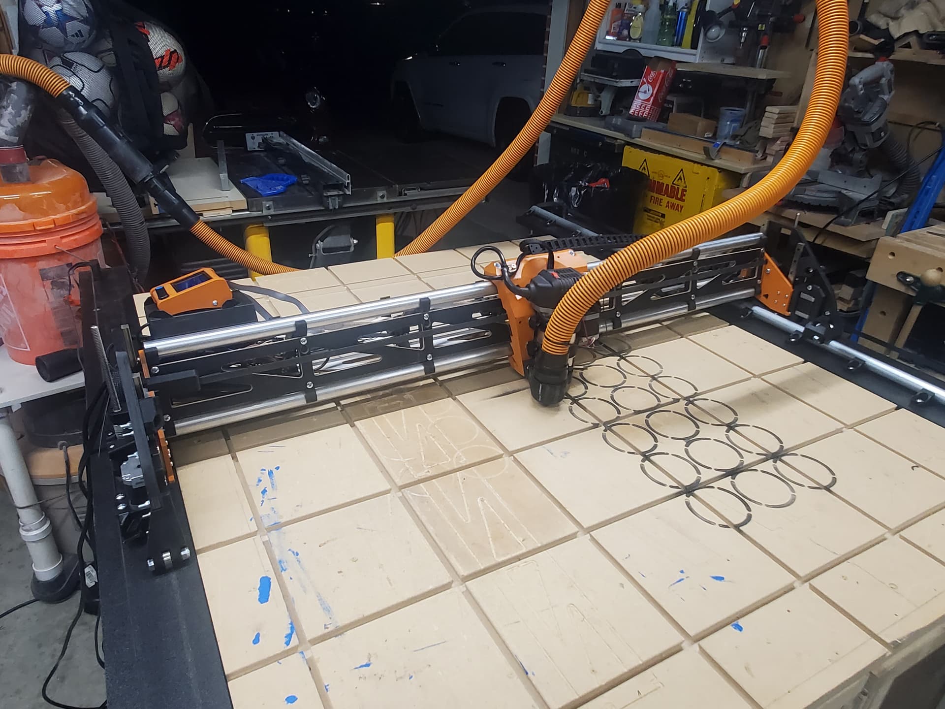
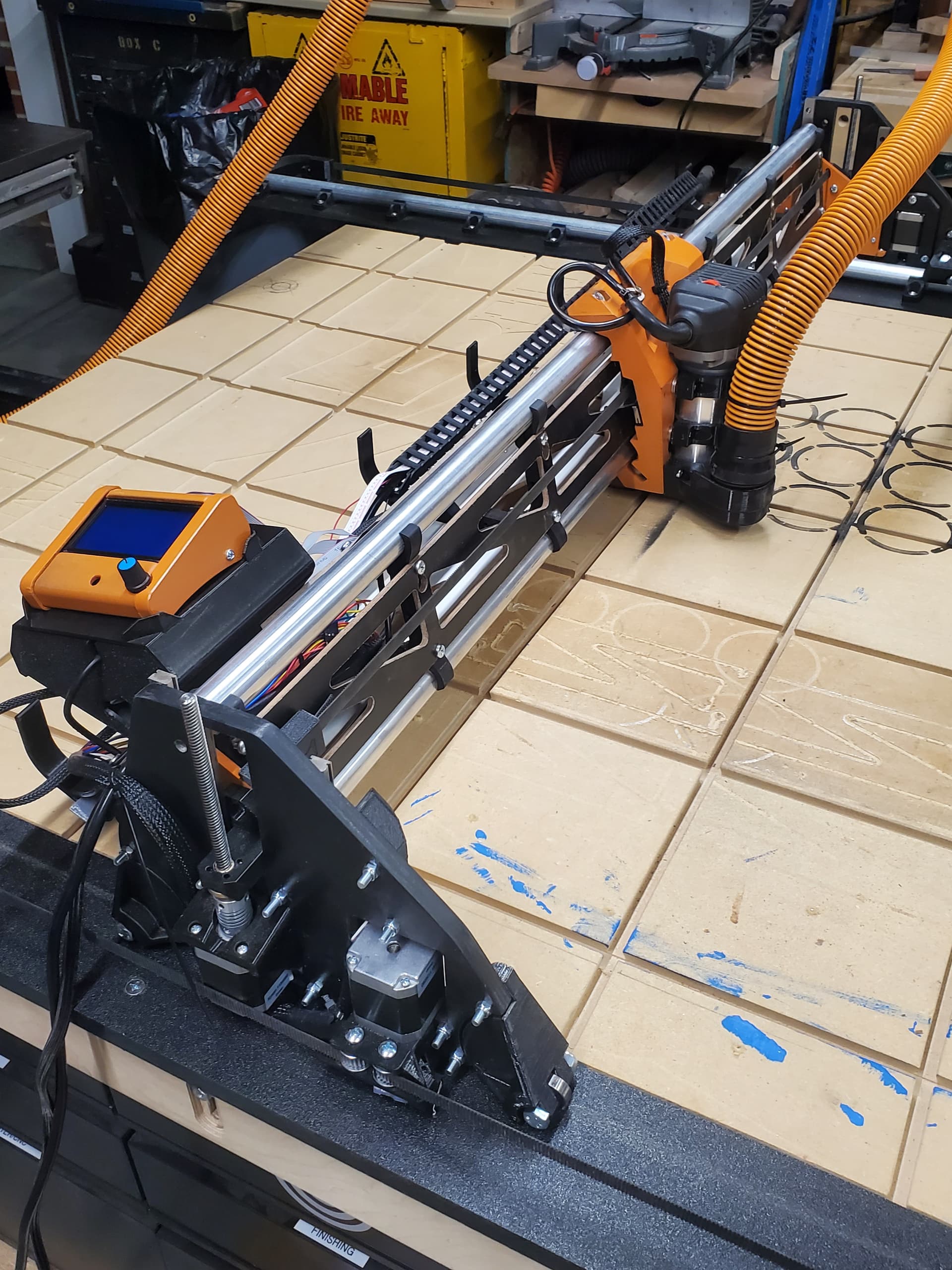
Now I wish I could edit the topic. I’m now complete with the upgrade, well almost, I’ve got a new Jackpot control board on its way! Plus some more wire control sleeve coming as well. So, here’s the almost final LR3 for the shop!
1 Like
you can edit, there should be a pencil right up there by the title!
@Ryan Dude, seriously, ordered my Jackpot on Friday morning and it arrived today! Holy cow! (My area runs mail 7 days a week - I’m not complaining!)
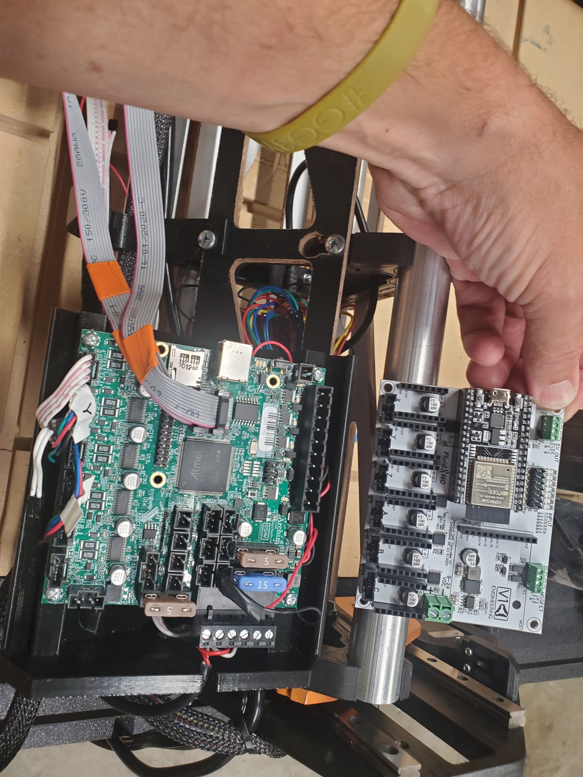
So for those who are looking at the Jackpot Board / FluidNC #Jackpot controller, here is a picture for reference. The older board is an Archim2 board. I was starting to get nervous after I purchased it, not thinking about the dog house for holding the board, but this should work out just fine!
4 Likes
Hope you love it!
Nice!!
Returning to this post, I will endeavor to summarize from my past posts and direct emails with Ryan about my LR3 adventure. The pictures above have not changed much; I picked up a 3D printer and immediately printed a control box for the jackpot and stuffed all the board and wires into it. I then took the engraving needed part to a friend who has a Thor sized laser table and had her finish my lid for the Dad’s Urn. He and Mom are now at final rest in the Columbarium at Willamette Nat’l Cemetery. That was October. And soccer season is over and I am finally ready to knock out projects. But first: calibrate the LR3 - here’s where it left off…
In my hope to build the Urn fully and doing a nice engraving for the lid, the X axis was drifting a lot. As the spindle went along and did it’s duty, the Y axis was happily contributing to the effort. But the X axis, after a run of code - the border box - did not find the mark to ensure the next line of effort was justified on the project piece.
So this post is a primer, as I will go into the shop and try the test again but Ryan said to increase motor power, I’ll do this and then run a test. Might be a day or two to get this back to speed - meaning my brain, not the tool. I’m too much of a hobbyist to keep some of this stuff in my head long term. So I need to jump back onto the trail I left and remember why I have the grey hair I do…
Last item from Ryan’s message -
Driver current…If you have had you board a while, I have increased the driver current on all drives to 680 and holding to 500. You can do that from the jackpot web interface and making sure to use my save macro button. If your steppers are not powered enough you could have skipped a step.
1 Like
I did a crown test again - a couple items I checked before I did it: Motor currents are all the same - 680 and holding to 500, each axis. Already set.
As I turned it on I did a homing and noticed the X Axis jogging rather jittery-like. Not smooth nor consistent - this is where I think my next adjustment might need to be. here are my thoughts on next steps. Confirm or provide other thoughts…
- Tightness of belt?
- Cleanliness of conduit
- Smooth running of bearings on said conduit
Picture of the crown test - it is definitely the x axis as all items are running in Y axis fine.
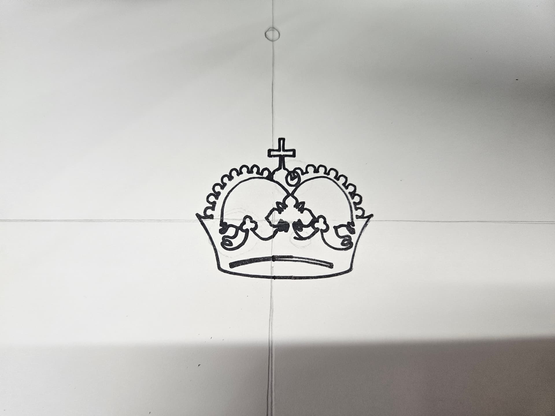
Pencil lines are the zero lines. I centered the crown at the intersection of the pencil lines. It came right off zero and immediately lost center.
Does your core move smoothly on the x axis if the belt is disconnected?
Did you loctite your grub screws?
1 Like
There is some resistance, as in I can’t just send the X carriage across the gantry freely. But it does run across with even force, but dead strip of that force strips.
Here’s a thought …
I know the LR3 is designed to run on conduit.
When I built my LR2, I ordered aluminum 1" OD pipe. And I had enough to use this for the LR3. Anyone think that this could be an issue? I’ve checked every other variable so far and this might be the only conclusion I can think of.
Without other thoughts, I guess I’ll disable and swap out. It might just work.
That is going to deform in a matter of minutes to hours of run time. It just will not work. Your beam will get loose spots.
That and it has very little rigidity, it must be very springy.
It is 1/8", 3.4mm wall aluminum. It fared very well in the LR2. I realized I needed to get thick with it - I just wanted a really smooth outside and I felt that aluminum was it. It has zero deflection over 47" span. That, and being supported now with the LR3 Gantry, it’s spiffy rigid.
This Aluminum is a perfect 1" OD where the EMT is actually over at 1.163" and the 3/4" is .922" OD. Not sure if I ought to swap out to EMT or not. Either way, another day for testing. Maybe I need to power up the X axis further than the 680/500?
No I did not use loctite, I’ll add this into my work tomorrow and see if I’m catching slippage on the belt. Thank you!
The .922 is how it is designed.
If you think that aluminum is rigid…the emt will shock you. The pressures you are using on you bearings must be very very light. I have personally deformed SS on my mpcnc just because they were a bit too tight, that would have been a nightmare on aluminum.
I have no issues with you using it if you are happy with it, but please do not recommend it to people that ask about it. It does come up occasionally, but I do not think anyone else will have as pleasant of an experience as you are having.