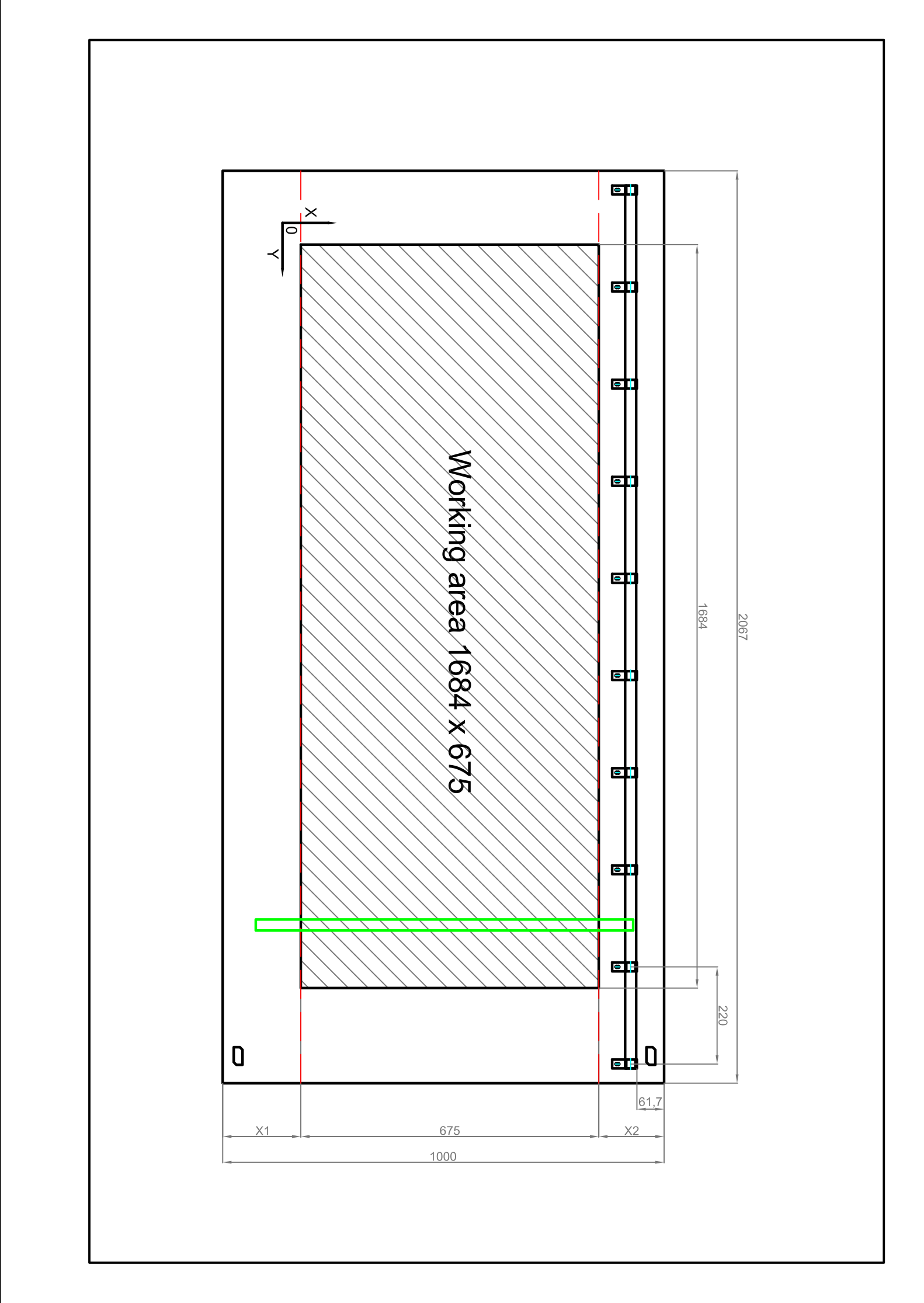
I’m working on making the LR3 with 655 x 1684 work area on a 1000 x 2067 table as per the following diagram.
Few questions:
I would like to separate the spoil board from the two external sliding tracks. I would need to know the correct dimensions for X1 and X2.
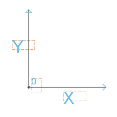
I have indicated the 0 (zero) point and the directions of the X and Y axes. Are they correct? On my MPCNC with the 0 in the same position I have the X axis instead of the Y and this makes me a bit confused. I would like the orientation to be the same, which is also the axis orientation of my drawing program, is this possible?
I saw the post Mirrored toolpath or axis - #2 by robertbu and my mental confusion increased!
Any help will be appreciated
Thank you My_LR3.zip (16.7 KB)
Your best bet to get an answer to your first question is to 1) have someone measure their machine, or 2) bring in a few critical components to a CAD program, and measure in the CAD program, or 3) build the Lowrider and use your physical machine to position the spoil bord. Suggestion #3 is safest since things like the router mount can have an impact on this measurement.
As for your second issue, you too have a coordinate system problem. Imagine you are standing along the X baseline. You want the origin in the lower left with positive X going right and positive Y going up. You need to reverse the direction of either your X axis, or your Y axis (not both). This gives you two possible corners to use for your origin, and the one in your drawing is not one of them.
This is the coordinate system used by any CAD program I’ve used.
Thanks Robert,
Regarding my first question, I hope someone from this forum can suggest me the correct dimensions, since I have to order the pieces already cut because I don’t have the possibility to cut them in my small workshop.
With reference to the second question, you are correct, my CAD coordinate system is the one you reported, the one I drew refers to the LR3 instructions, assuming I understood correctly.
The coordinate system I would like to have is the standard CAD system
which will save me mental confusion…
Do you think it’s possible? How could I do it?
Thank you
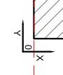
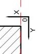
Not just possible, but necessary. The first step is to move the origin conceptually. Looking at your drawing, the origin corner should be flipped and moved to the bottom left, so it would be like this:
As far as making it happen on the machine, it is a simple matter of making sure your steppers move in the right direction relative to the origin point. If they move in the opposite direction, you can simply flip any stepper connection(s) to reverse the motor(s).
Based on your drawing, the alternate origin corner would be upper right, which would also work.
My answer to your first question about X1 and X2 was based on confusion on my part. The dark green color of your icon is also associated with a direct message, so I thought you had direct messaged me for an answer rather than asked on the whole forum. I would not have put in an answer to the first part if I’d known your questions was posted to the entire forum.
Many thanks Robert for your quick replies and for solving one of my queries.
I hope someone who has built the LR3 before can help me with the last one.
If you don’t get an answer from a LR3 owner in the next day, I suggest you open a new topic just for your first question. Put the image directly in the question, not in ZIP file so they can see what X1 and X2 represent at a glance. I’m sure some LR3 owner will measure for you and give you an answer. I suspect your first question is just buried at this point.
The LR3 calculator says your strut plate length and X rails are 855mm. The width of the carriage is 180mm according to that image. The actual part (at least on my low rider) is a little wider than that, closer to 190mm. The X endstop determines where the carriage stops on the left side, and the carriage will bind at some point on the right. The endstop can be adjusted a little bit, and there are endstop trigger lengths to consider. Also, the minimum size for your LR3 table is based on fitting the belt mounts, and mine are not exactly on the edge. So measuring on my machine won’t be that helpful.
Honestly, it is all just a bit too messy for me. I don’t want to give you a number, because I think adding 10mm to either end is going to be much easier, and you won’t have to stress about it so much.
I am going to say X1=X2=162.5. But I would make them 10mm or even 20mm shorter, and make your spoil board that much bigger.
You work area would still be the same 675, but your spoil board will be bigger, 715mm, and then X1,X2 would be (1000-715)/2=142.5. That should give you plenty of wiggle room to mount your belts, have any thickness plates you want, and adjust your X endstop to fit your needs, without ever being able to cut outside of your spoil board. 20mm is probably more tolerance than you need, because it is really only the asymmetry after all the mounting and adjustments. But again, I just would not be that worried about over doing it by an inch.