Disclaimer: This design was entirely an exercise in learning both CAD/Fusion 360 and developing a tangible understanding of what can be done with 3d printing in a functional/structural capacity. I don’t really recommend it beyond the “hey, that kinda looks cool” factor. In fact - most repurposed tables and workbenches are likely a much better approach in terms of both cost and function. In other words - I did this mostly for fun and learning ![]()
So first thing after receiving the kit from Ryan I slapped the LR3 together on a 24”x48”’ 2x4 Basics workbench I already had which I built some temporary wings for. This was a good starting point to gather some familiarity with the design/process for me, and actually worked rather well, but suffered from some shortcomings as a result of being a repurposed table. For example: It had a rather unusual usable cutting area, poor flatness and lacked a good hold-down system.
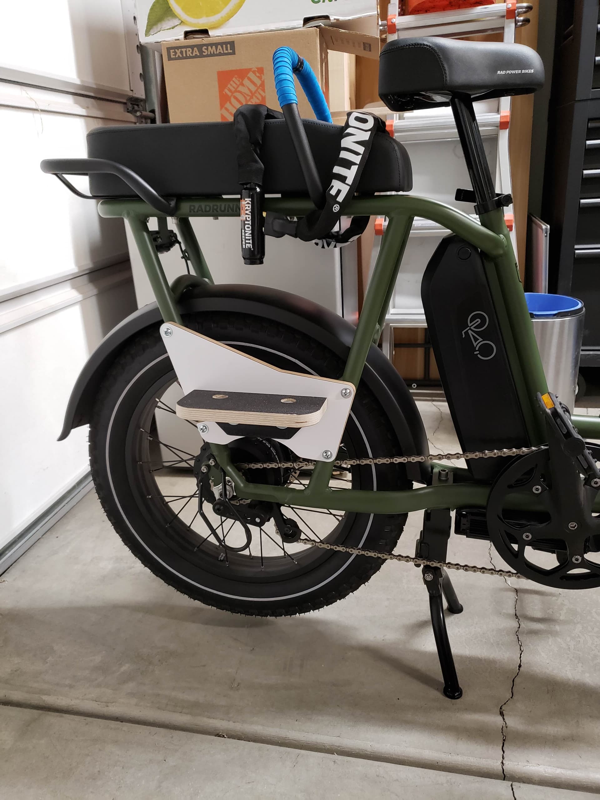
Here I am using it to cut some plates for making foot boards for the kiddo on my RadRunnner:
The only modification I made at this point was a small bracket for engaging the z limit switches, this was actually my first ever 3d printed part!
I ran the machine this way for a solid month or two while I got to work learning how to use fusion 360… and a 3d printer. I knew I wanted to rebuild the table to have a work area to accommodate 1/4-sheet material, and to be able to roll the machine around as my space is pretty limited.
I initially considered just making the 2x4 basics table into a 65”x40” workbench and laying some strips down to raise the rail and adding a custom spoilboard. I think this was actually a really good idea, but it lacked the “cool” factor and didn’t really provide me with an engaging way to learn to use fusion and the 3D Printer.
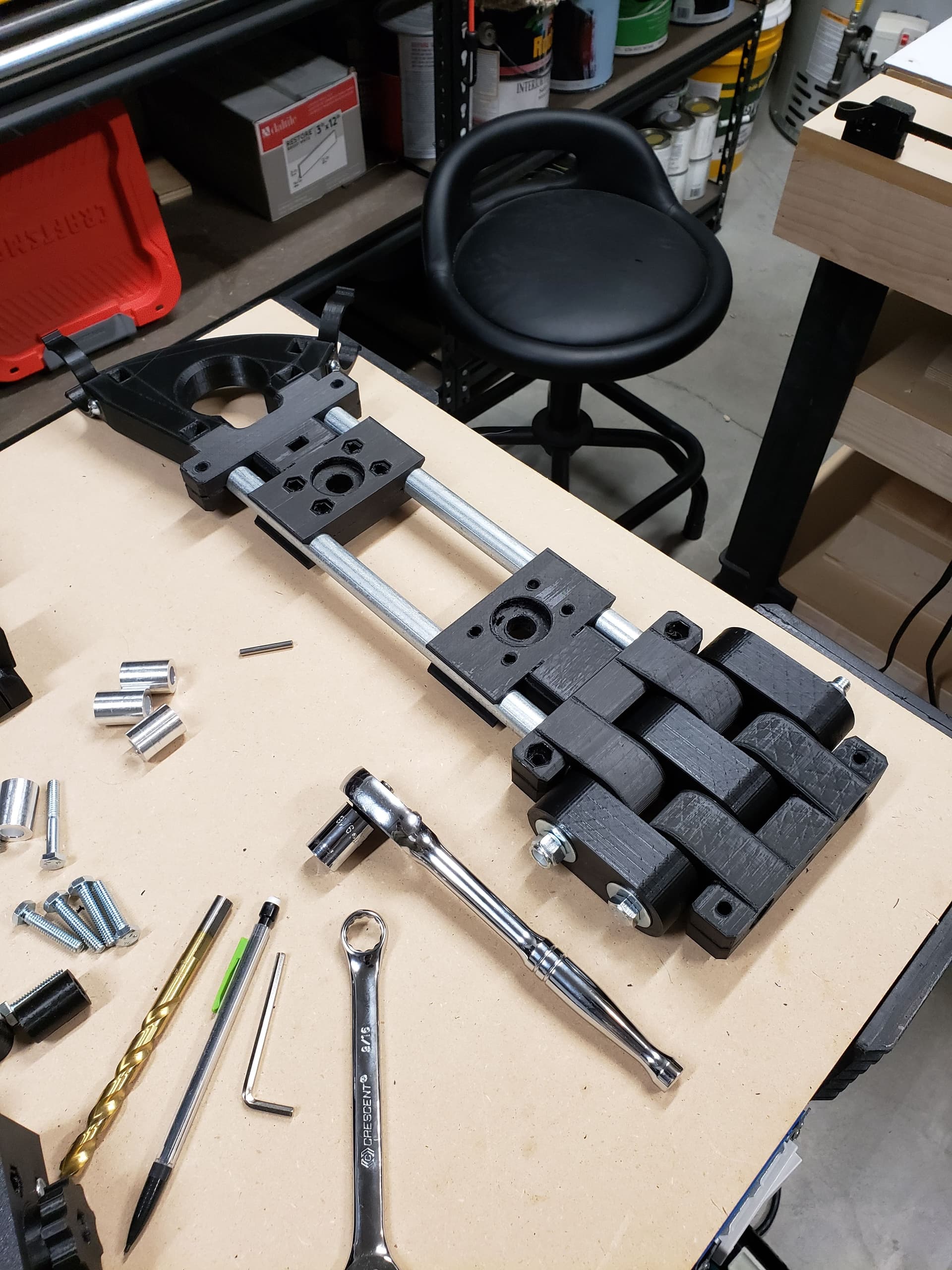
Since the main reason I bought this machine was to design and build my own furniture, I decided to
try to come up with something that would test/develop a lot of the techniques I would use in that process. After settling on the more complicated approach here’s what my initial idea/design looked like:
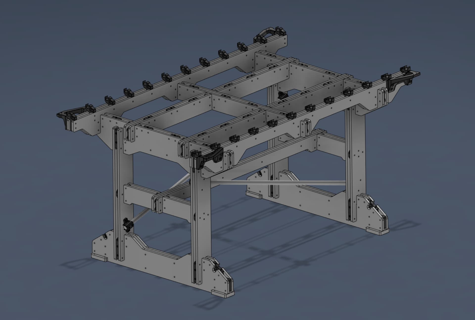
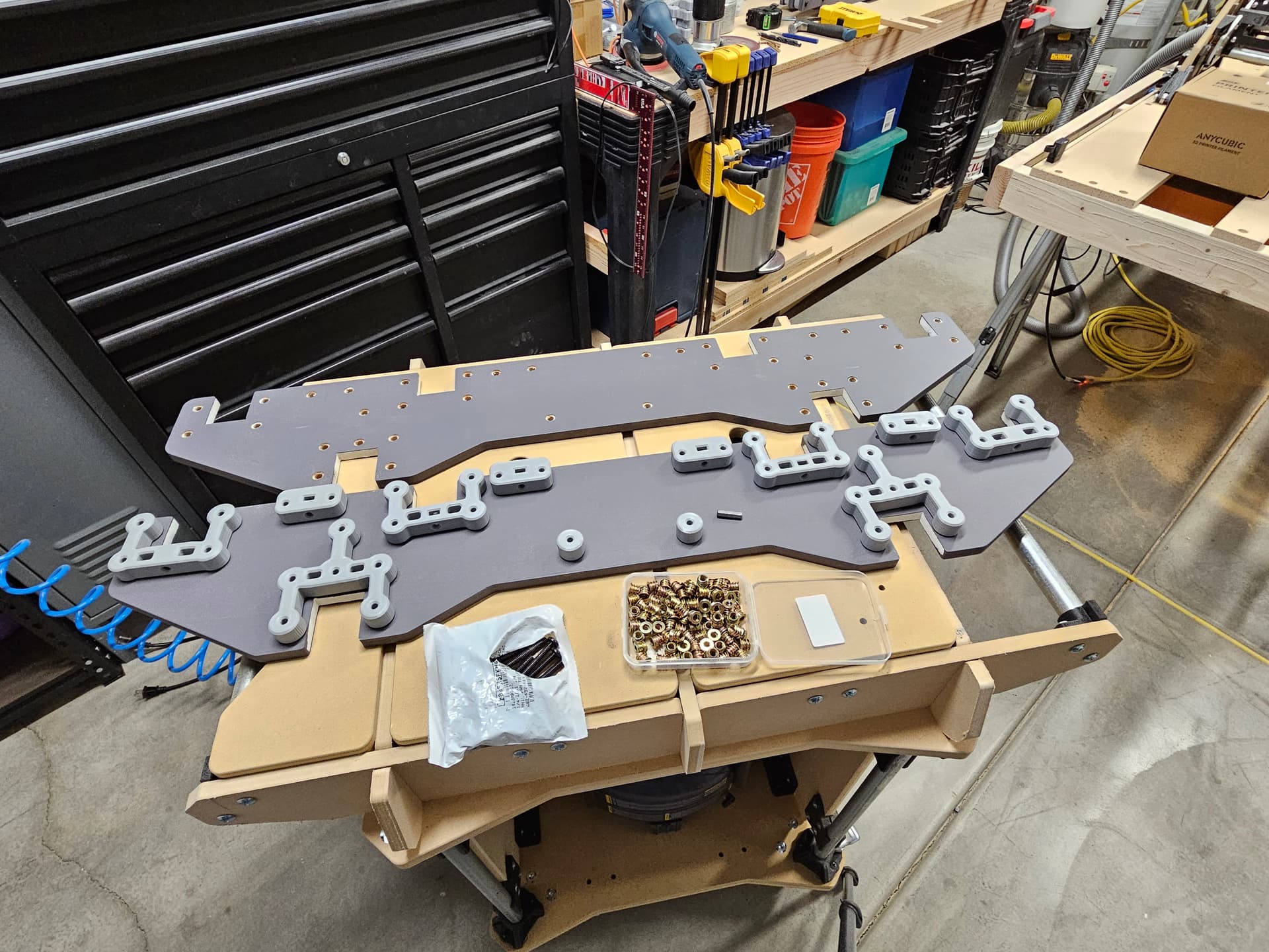
This design incorporated 3D printed brackets with captured nuts sandwiched between two layers of MDF with one side having 1/4-20 threaded inserts for assembly. This would allow me to easily bolt/unbolt everything together.
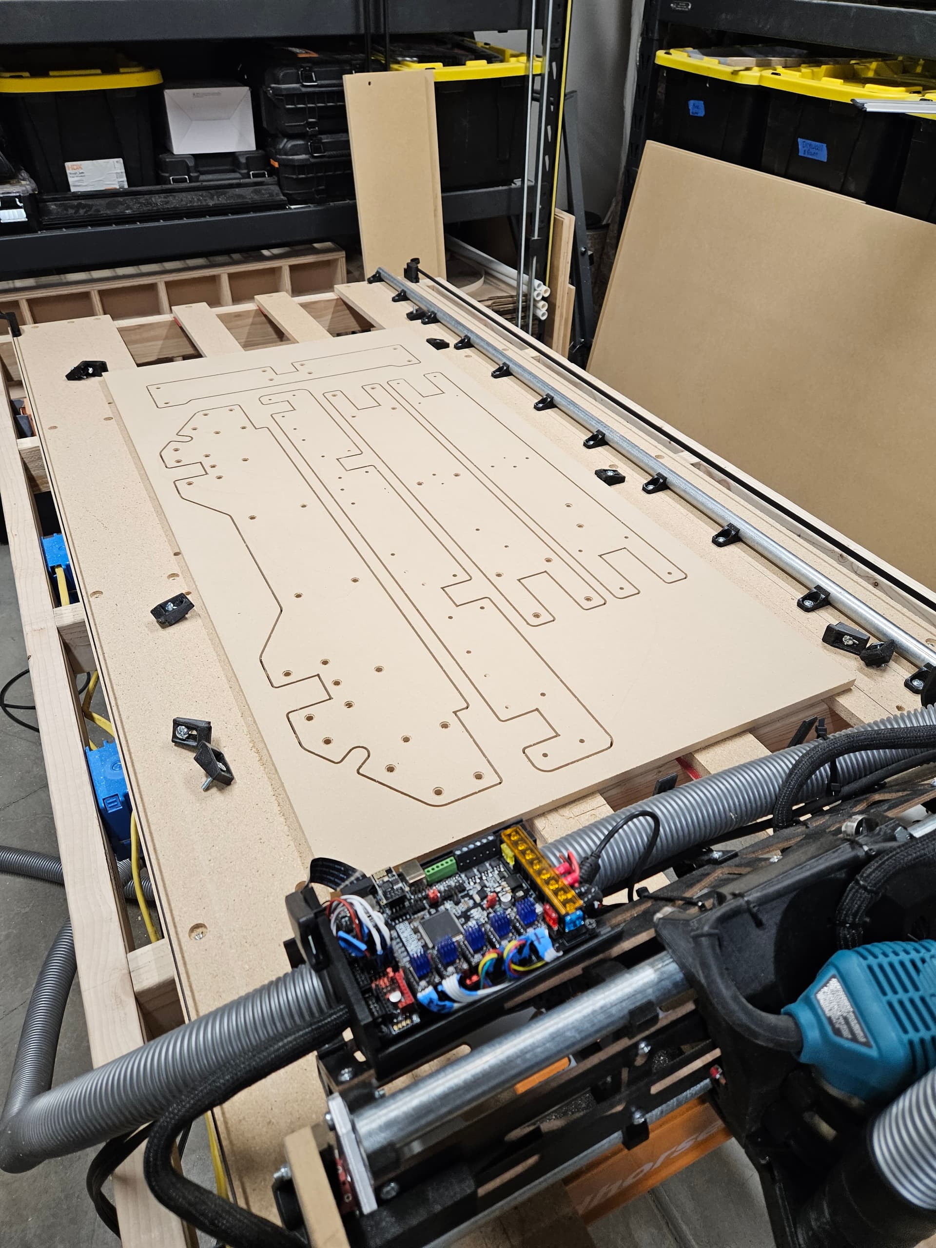
I could cut this on the machine I currently had using the “tiling” method, but that sounded like a great way to introduce error into the components and almost every single piece would have required a tiling cut because my current max cut length was 34”. So I decided to rebuild the machine as cheaply and simply as possible to allow for the full 68” cut length I required using 2x4’s and some random left over particle board strips and saw horses.
This is what that looked like:
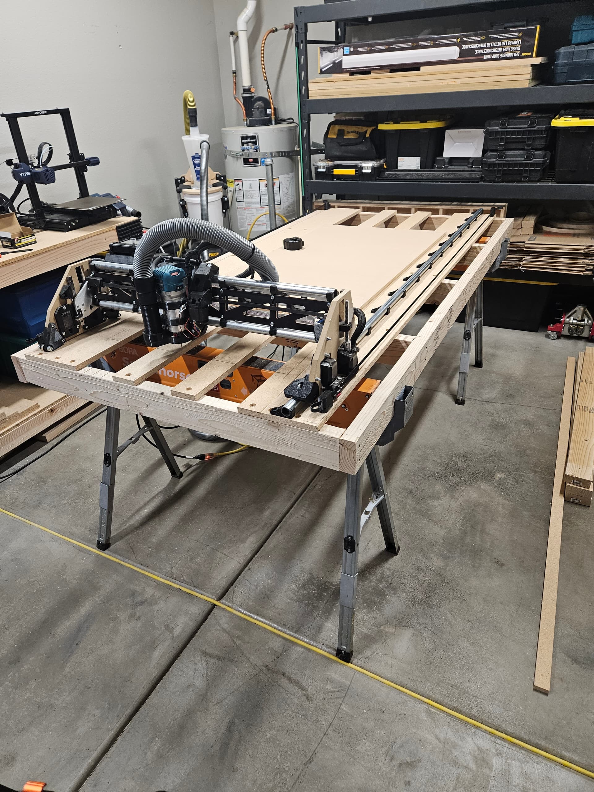
I went around and shimmed the strips using playing cards to get the whole thing roughly level and I was actually pretty surprised at how well the thing performed. I think this is a really cheap and solid temporary setup for most people to use for cutting torsion boxes to use in a final build scenario.
There were a few moments when I thought to myself “I could just be done now, this thing works fine.” Any type of fast small rapid cuts would be problematic however, as a small breeze would rock the table front to back without cross bracing - this wasn’t an issue for the profile cuts at the speeds I was running however.
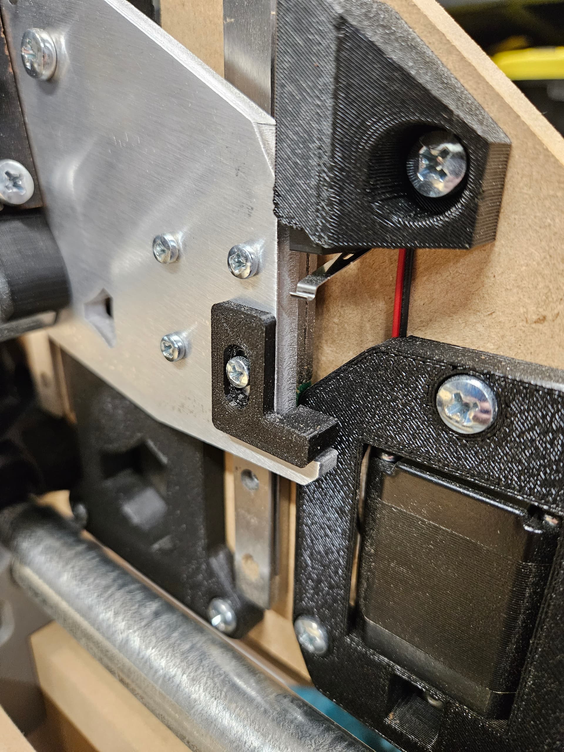
Here’s a shot cutting the new table components, even the pocket depths for the threaded inserts were surprisingly consistent for such a wonky setup. (it was around this time I switched to the headless design as well, which is why you see the exposed control board.)
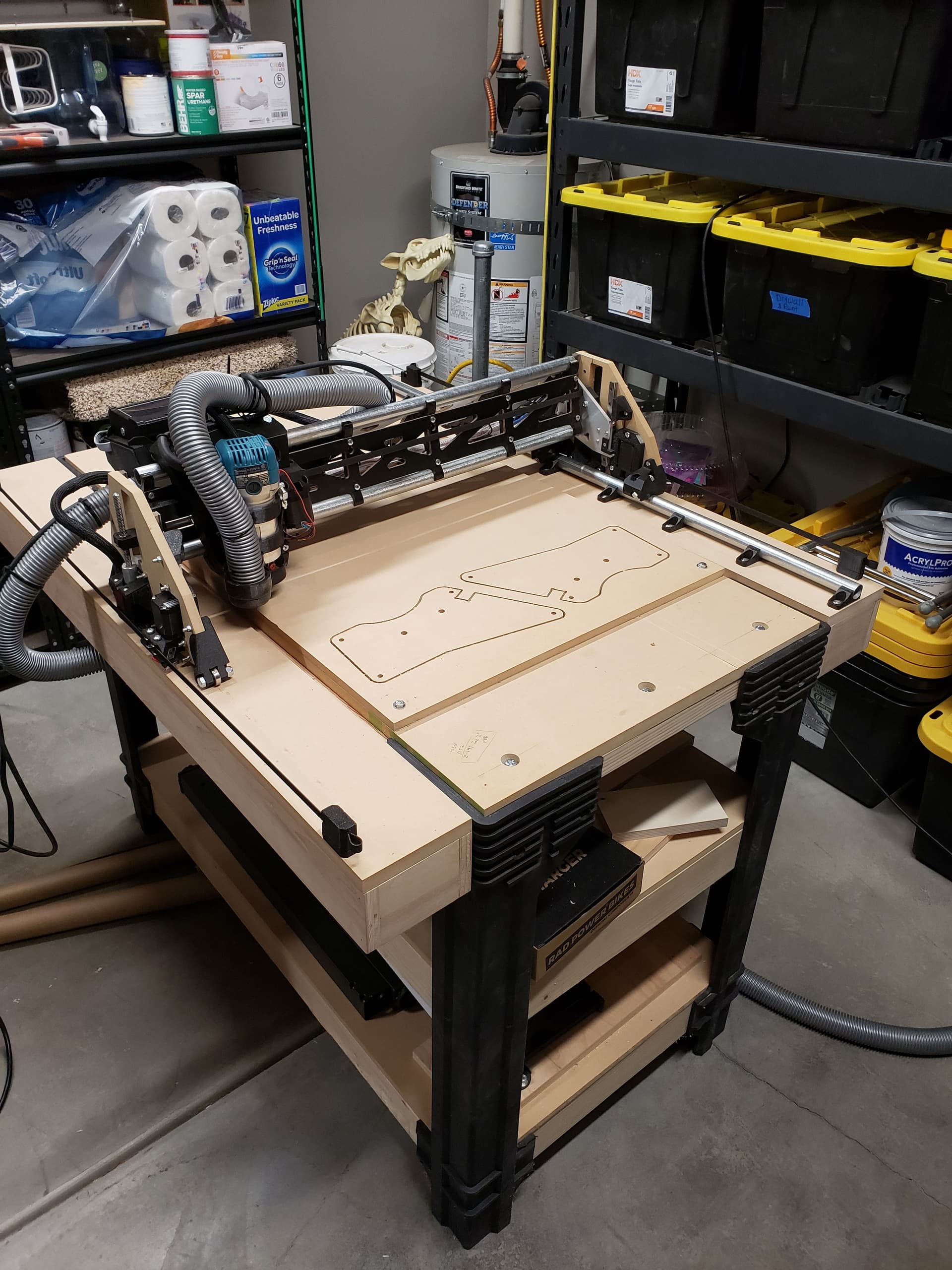
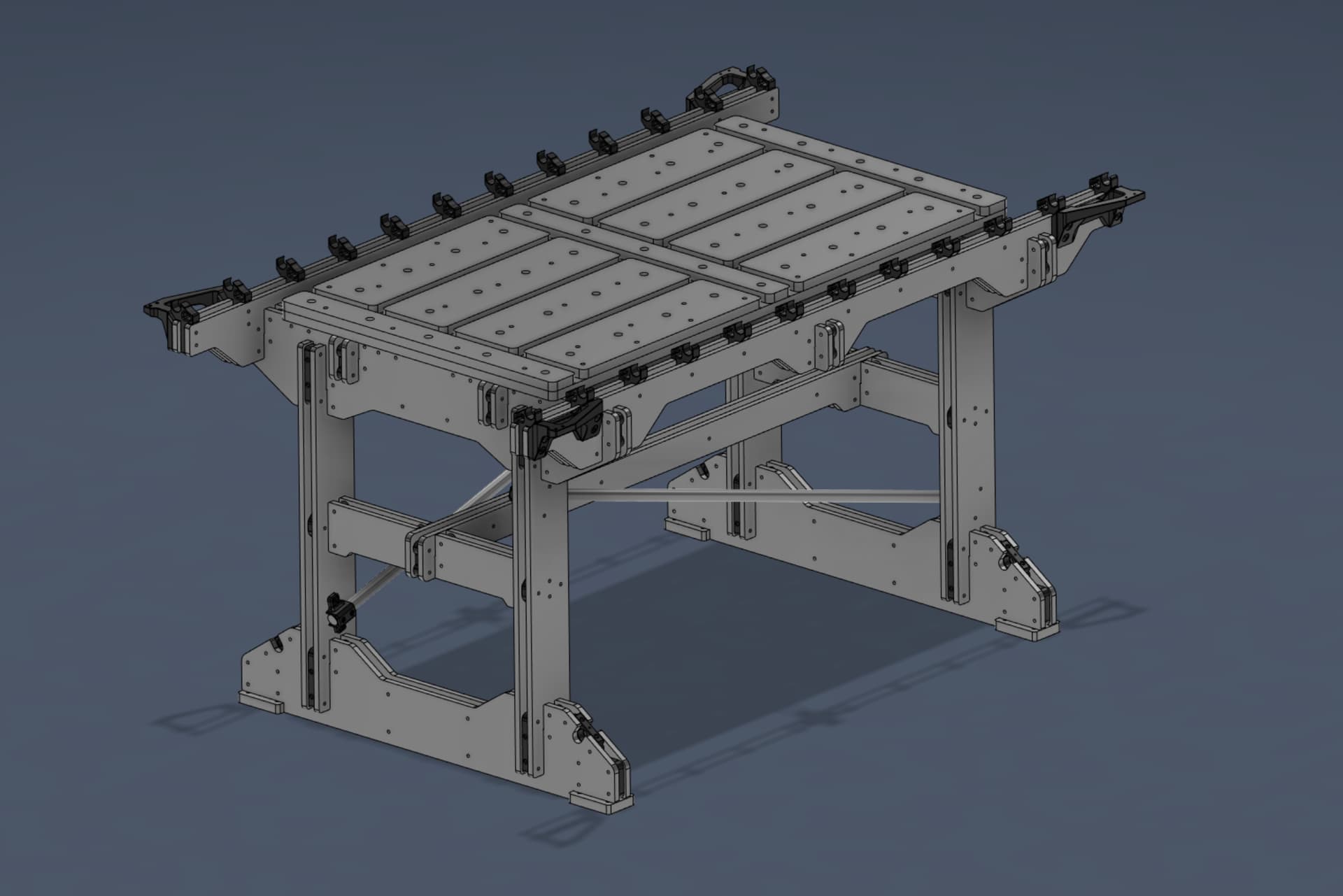
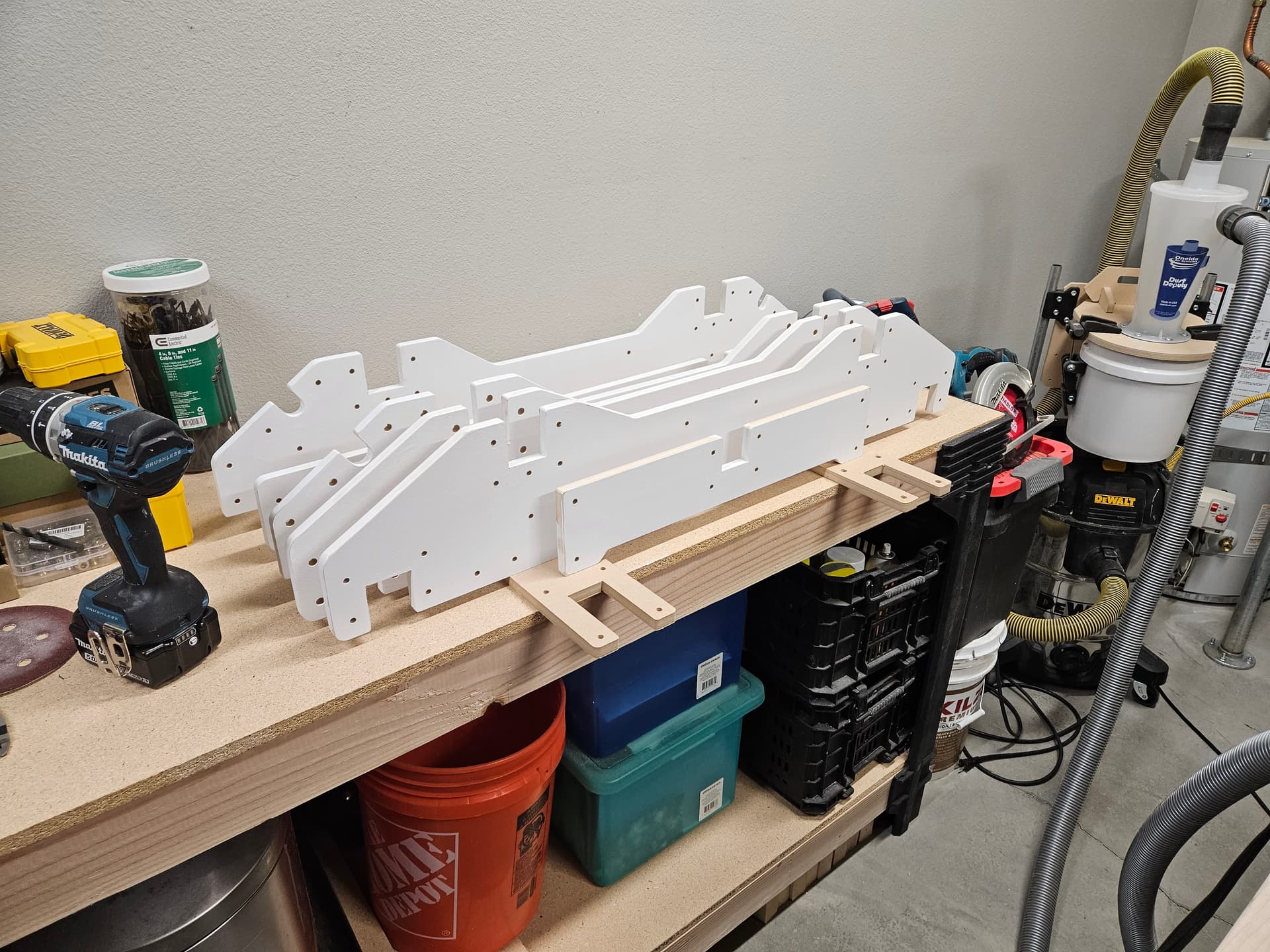
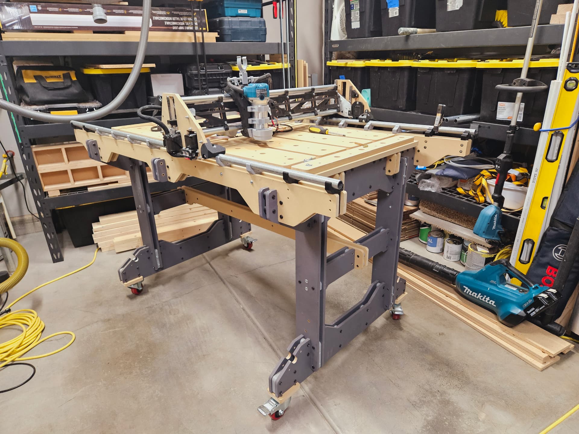
Next I painted with some acrylic based primer and assembled the components:
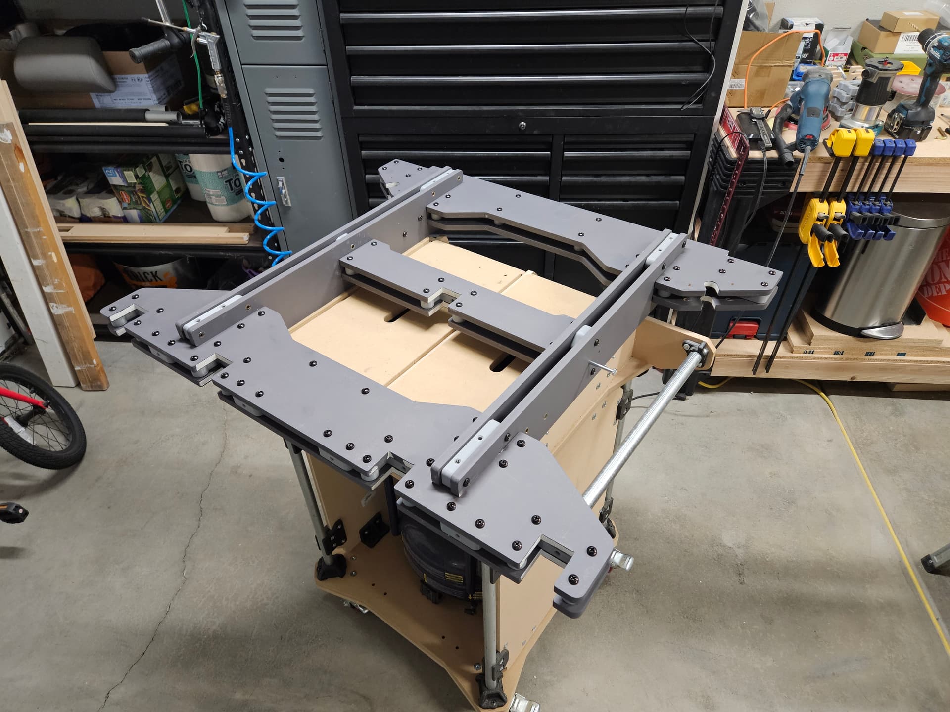

The spoilboard is set up using the same threaded inserts as the rest of the assembly and this allows me to use some neat 3D printed hold down clamps. Most of what I want to do utilizes sheet goods so the spoilboard is layed out to make securing anything from a ¼ sheet and under fairly simple.

I decided to try the build using two rails to see if the accuracy of having everything cnc cut would prevent any alignment issues. While it seems to be fine so far - I did anticipate the possibility of needing to switch back to the original design. In that case I can swap out one of the “wings” fairly easily as it’s all simply bolted together.
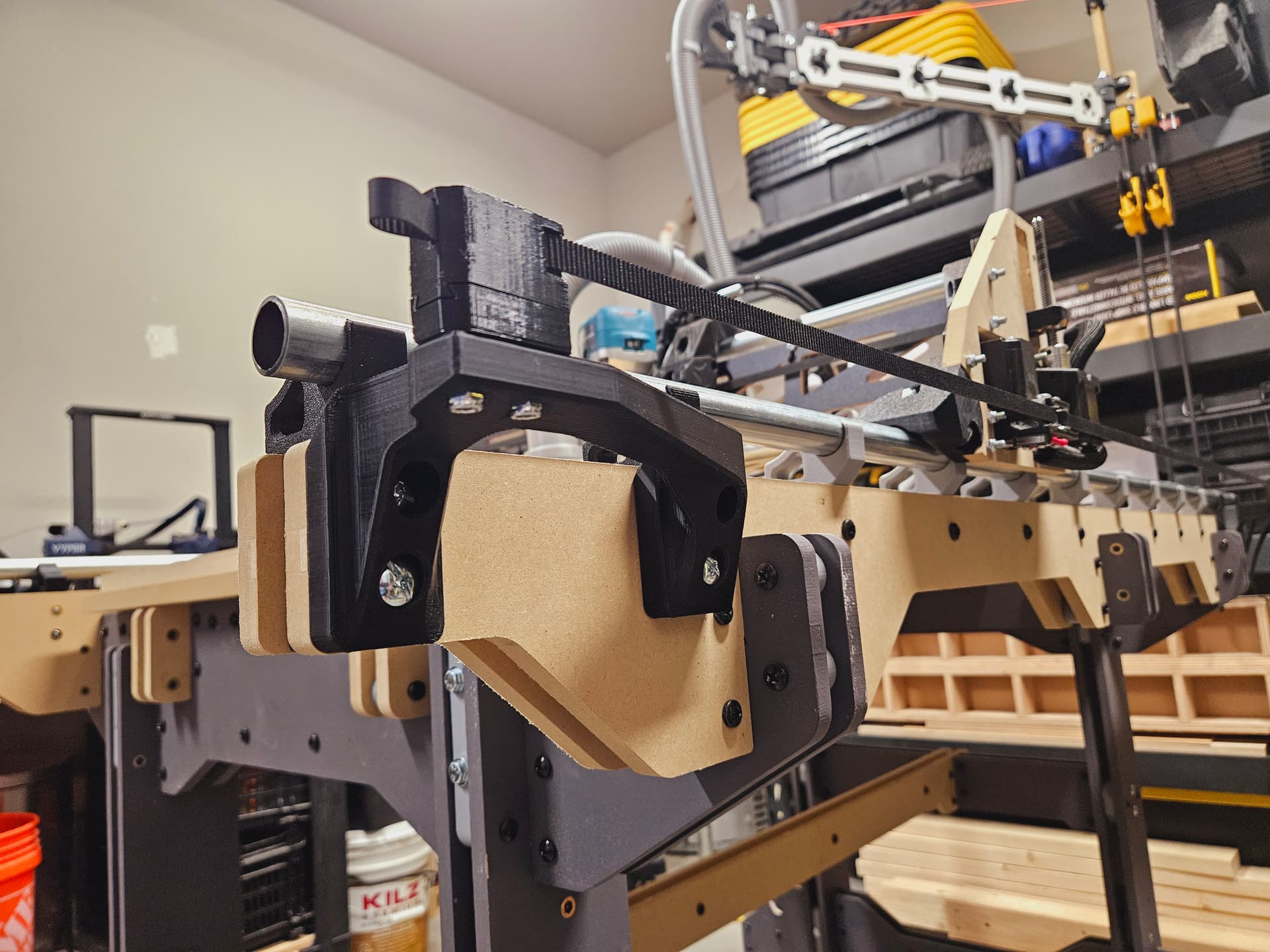
Next you can see the brackets for holding the belts and the cross-bracing for the legs. Being able to roll the machine around in my small space is absolutely amazing - and the bracing makes the whole thing feel pretty solid.
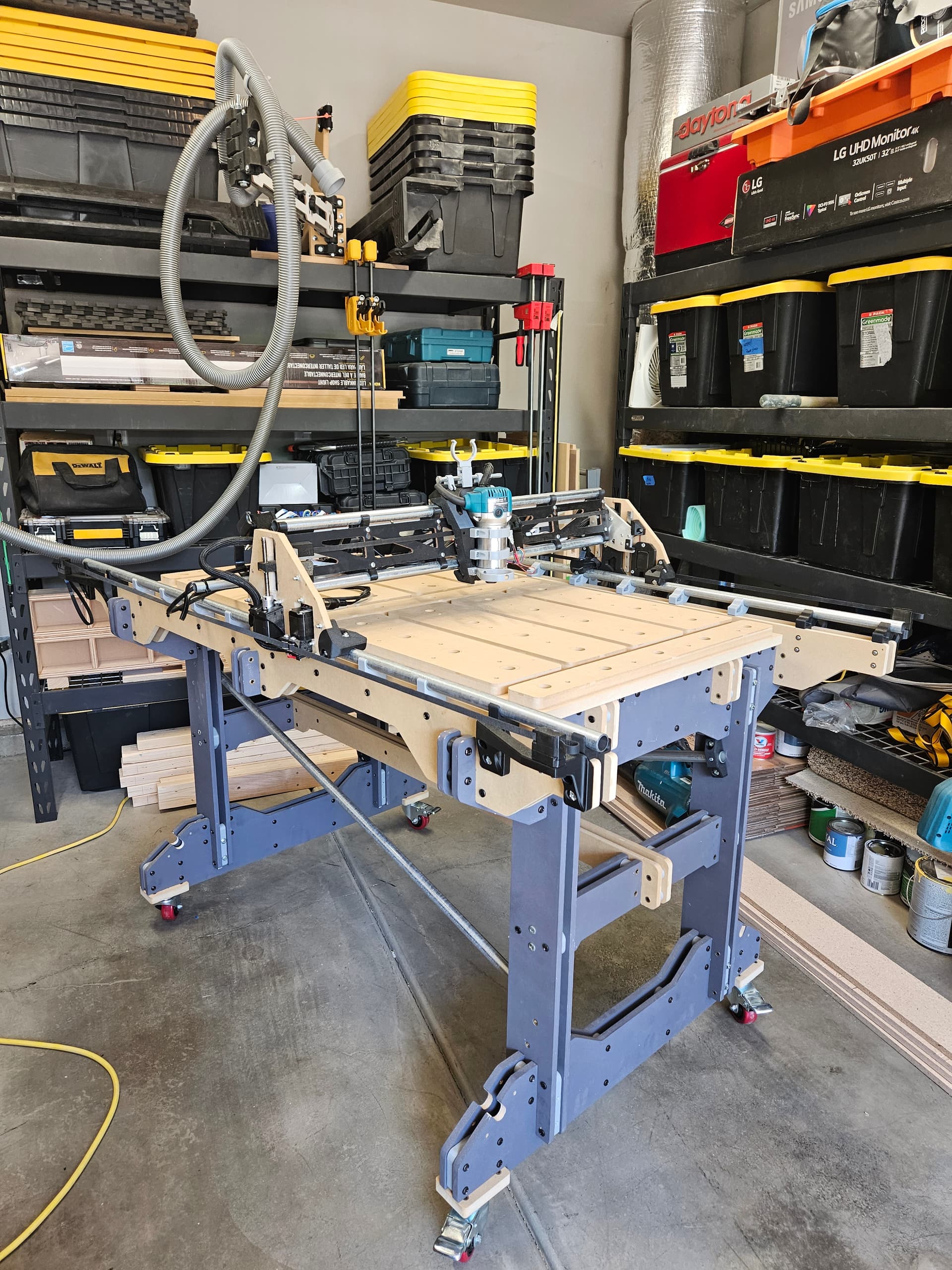
I still have to design the power/e-stop switch box and replace the electronics enclosure since I went headless and want a better setup for using the sd card.
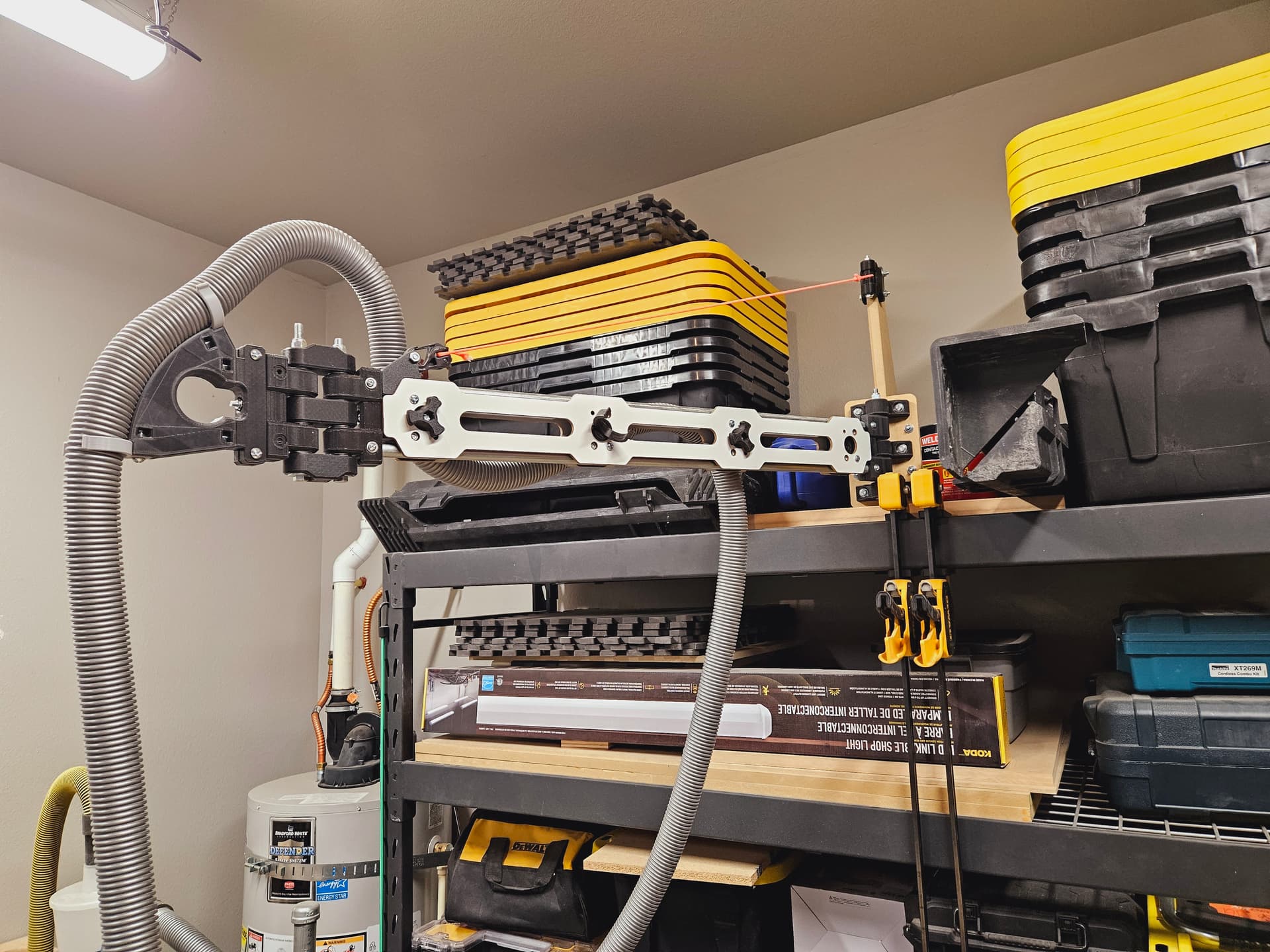
I’m quite excited to be moving on to designing things to actually make with the machine now that the majority of the table design is done. The next project will probably be building a dust collection tower for mounting the 3D printed boom arm you can see in some of the photo’s - more 3d printed MDF combo stuff.