Earlier on the “best dust 2023” conversion i did explore that with a picture. Its definitely an option. I will have to see.
Unfortunately, for the front mount version, there is still that vac house to deal with.
I will get the thing i bit further along and see where I end up.
So its funny where you get insperation from somedays.
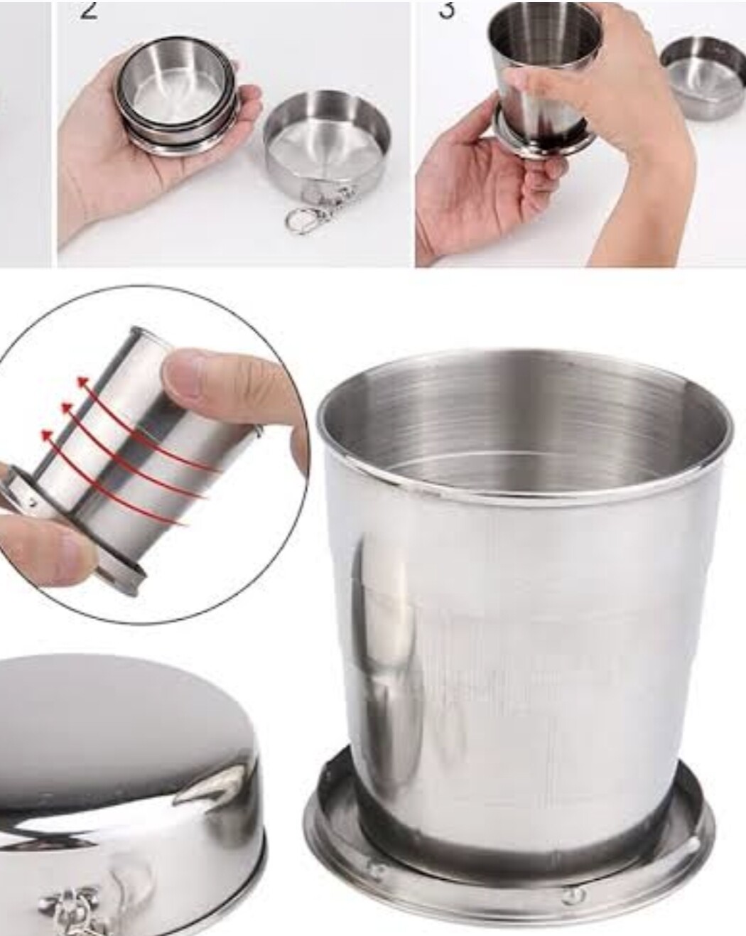
I was watch a movie or something and it ihad a set of russian dolls in it, and that got me thinking as i saw somwhere metal version.
So a bit of searching and found a picture of one.
Well it made me think of the bellows and connecting the dust shoe to the router.
So far i see it being printed out of PLA maybe it might be easier to fit each time and magents at each end to join ot to the dust show and the core.
I like that approach, really the brushed skirt only needs to be 10mm or so just to stop it catching, and it’s only needs to telescope the length of the bit.
“I keep saying you don’t know where you inspiration will come from”
and love love fest i am having with @DougJoseph idea, has inspired me lol.
I have been talking about the bellows that will connect my dust shoe to the CORE, and talking about printing it in TPU, TPU is not the easiest thing to print, well guess what Doug has on his dust shoe…
That’s right a bit of that clear tube connecting it from the core to the dust shoe!
Sure it will take a remix and maybe a larger size that my 51mm (2inch) tube, i will have to measure that when i get to that point, but it comes in so many sizes.
remix with a couple of flanges to suit the dust shoe and the bottom of the core/ router and, ka-pow, you have a bellows!
Ok, I need some information from you experienced people out there.
So the original dust shoe and the recent ones are designed to fit in the area below the router on that third bracket. As best as I can see it they are sitting no lower than the CORE other than there brushes.
After modelling it, the issue is the back of the core, my router nut sits just up from the bottom of the core. Depending on how thick the wood your are cutting is, the core comes pretty close to the wood.
Could you experienced people place give me an idea of the minimum space between your core and the cutting surface. My CORE seemed to have come pretty darn close to the wood.
Both ways I have modelled it is making it look like the shoe will have to be bigger than the bottom of the CORE, so the CORE can slide down into it, to some extent, with a bellows around the router of some sort this should not be an issue.
but visually its going to be huge.
I have worked out a simple way to lock the core to the dust shoe assembly with the hoop at the top. It will allow the Z to move up and down and still keep them aligned. Sure it need some refinement, but I cant tackle that till I have sorted out the dust shoe.
So next time you are cutting can you have a look at how close your core gets to the cutting surface for me please?
I guess I can take advantage of the standard dust shoe and slot it into the same space as its currently occupying, but the dust shoe would have to be much longer in the Y direction as you can see from the renders here. With the solid hoop indexing it to the CORE the slider would get out of sync. but everything would need to be quite tight to stop the dust shoe from wobbling around.
If i am right, and i am happy to not be, then the rear mount version just got a bit harder as it would have to wrap around from the front to the back without going under the CORE, probably under the X motor.
I hope I have had too much sugar and i have got it wrong…
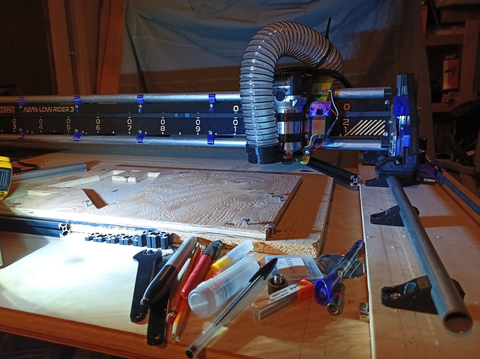
Pic of my setup showing 5/8" spoilboard, 3/4" ply for Y rails fastened to kinda torsion box. Left 2020 in pic for scale reference. Sharing pic since everyone has different approaches.
For my build, probably diff from yours, Bottomed out gantry ends up with bottom of Core being ~16mm above spoilboard.
I’ve had a lot of cut jobs where my bit was short, my and material was thick, and my core was nearly touching the material. In order to try to add bristles without taking away this needed functionality, I made my new dust shoe design as thin as it could possibly be, which is to say the minimum amount of height needed to properly grab onto the “foot” that the shoe slides onto, and that gave me a few millimeters to add some bristles. However, those bristles would probably have been too short to do any good, so I made them slightly longer. The bottom line is that if my machine, with my new setup, needed to get that close, the bristles would have to bend, and I am hopeful that they would be able to. I have thought seriously about applying a little bit of heat, maybe with a heat gun, and manually putting a slight bend in my foam bristles, so that they would already be started toward bending in one direction. In the 3-D model of the printables listing of my ongoing work, the gray part at the very bottom stands in for the foam bristles. You can see how much the dust shoe has its bottom edge above the bottom of the core, and the foam bristles extend just below the bottom of the core. I am in hopes this setup will let me get as close to the material as I was getting before.
@azab2c thanks yep, worst fears confirmed. damm. ok, i think i can work with that.
Like I said now i have two options that i need to play with.
Make the dust shoe the same as the original, riding in the location as the original and that makes it virtually the same as Doug’s and i don see it being any better.
Make the dust shoe bigger than the CORE so the CORE can lower into the opening.
In option 2, i can see that i would probably be able to make a section in the dust shoe where the CORE would “fit into”, leaving only the thickness of the print in that area between the bottom of the core and the cutting surface.
Then the rest of the shoe could be modelled to be as high as needed. Doing it this way the opening will be no bigger than the current opening. Also this option would allow for the rear mount version as well.
Unfortunately this is now going to take quite a while for me to model, i will have to do a quite a bit of learning around the use of “mate” connectors in onshape (fixing parts into one plane and allowing them to move in that plane. i am sure the other brands do something similar) plus i am going to need to model the router, then assemble it all into a working model to get all the heights right.
I am not afraid to admit that is a step above my current skill level. So its going to take a some time to accomplish.
Essentially my plan is to now create a dust shoe that is bigger that the core with the embossed section of the core in the surface, the shoe will be a little bigger than the bottom of the CORE, but not by much, and that wont interfere with the X travel, but will with clamps and stuff so bristle length will have to be quite long to be able to deal with that, throw in the torsional forces that are present when the shoe and brushes are forced over a clamp and rigidity need to compensate for that, so i am not sure this will get off the design table for that exact reason.
Still worth while for the learning on my behalf. so lets see how it goes.
With the utter success of @DougJoseph dust shoe and looking down the barrel of a new far more time and stressful job, I have decided to put this on the perinate back burner.
I will print his version and test it for my FrankenVac setup (with the stupid amounts of suction i have), for what I do and the amount I use my LR3 I don’t see any reason to continue to develop this as it will not really do anything more than doug’s version and be far more complex.
thanks to everyone (including doug) that supported the idea, this is such a great creative space.
In the design approach that I followed, there is a weakness, if you will, and that is the drag friction of the shoe as it slides on the material. This can be overcome by the strength of the stepper motors, however, it means that there can be stresses that can tug at the shoe to get it out of alignment. The design track that you were following had the advantage of being able to set the height just off the material and not have very much friction. So there’s a lot to like about that. It is a more involved, somewhat more complicated system with some hard-to-solve bits. I certainly understand how stressful and time-consuming life/job things can be!
Yes I can see your point regarding floating over the surface.
I am still going to play with this in the background, but with the new job I doubt I will have many spare cycles for this. I really need to get my MK4 up and running (still waiting on my upgrade kit, not impressed) and then I can print to my hearts content.
I would love to have a 3d environment setup to be able to try these ideas, and I am slowly building that up, but the CAD skills are not as advanced as yours, lol. Once I can get a printer again I might be able to get some time on the couch at night when the GF is watching tv that i am not interested in. Maybe then i can make some progress on the design.
Cutting 18mm plywood with a 3.175mm endmill lets you come very close, around 1mm or so if you want it to have a tiny bit of hold in the collet, which works without bristles or the very thin TPU bristles I have been using lately. If you have stiffer material like Doug you might need longer endmills.
I liked your floating Z Doug. Very well designed.
Not sure if anyone’s thought of maybe embedding a stepper motor to the core or adding one that lifts or drops the vac in sync with the Z?
So when Z drops, vac lifts the same amount and vice versa?
This could also maybe be gcoded of somewhat to raise when close to edge of materials and raised very high for tool changes??
Suppose you would need an additional driver for this on skr pro?
This very idea was initially suggested by @jeffeb3 if I’m not mistaken. It would be essentially the same signal as the existing Z steppers are getting, but just with the wiring flipped so it is moving the opposite direction of the Z steppers. Anything is doable, and as always the devil is in the details. In this case, the details include that we are doing all this on the side of the core that normally gets homed against the X-min side of the gantry, and in my latest release of the floating-Z dust shoe, I trimmed out all the fat to get it to home closer, and while I’m very close to homing as near to that side as without the mod, I am still having a very slight amount of loss of cuttable area. Bottom line is the real challenge would be finding where to put that additional stepper.