LR2-LR3 The Longest Conversion (AUS)

I was putting my table together yesterday and started thinking about skinning. I will glue and nail the bottom on, but what about the top? Permanent- Glue and screw, when the glue dries remove the screws, or swappable- deep counter sink a bunch of screws in the surface?

1 Like

On both of my LR3 I took and countersunk the screws as far as my countersink bit would go. That keeps the screws down plenty. No glue. That way when I surface enough off that its time to replace it can easily come up and replace with a new sheet.

1 Like

Does not matter, it’s going to look good. :smiley: Who needs to actually cut stuff anyway? :stuck_out_tongue:

I just put another spoilboard on top. :smiley:

1 Like

Well, yup I do think that is the best idea. Glue and countersink the first thick one. If it even gets too thin just surface and drop another on top.

Thanks!

3 Likes

The trouble with no permanent top skin is that it doesn’t stay rigid while you are “re-skinning” it so you lose the benefit of the torsion effect… I am just gluing and clamping 3mm MDF skins top and bottom, then I’ll use a screwed 16mm spoil board (with a couple of plot twists) into the subframe…

I’m using the LR2 table frame, and still have the possibility of tilting the top it as originally planned if I need to minimise the footprint a little (unlikely now that I’ve reshuffled everything in the shop).

On the LR2 the spoilboard was a “press fit” between the glued “tracks” which were also 16mm MDF. Arguably it was a complete failure as I didn’t want to risk damaging it so I used to clamp another board on top to protect the spoil board! :thinking:

This one will have similar permanent “tracks” and the spoil board will be in three identical pieces, each roughly 500 x800 (screwed).

That will allow easy replacement, flipping or swapping of any panel without having to replace the whole board when just a part of it gets chopped up, and more importantly I can buy 600 x 900 or 1200 boards that are much more easily handled than a full sheet.

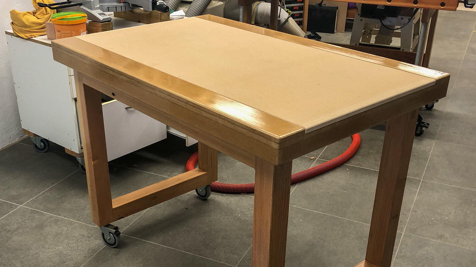
At what point does your table get too high to see over? :smiley:

Here’s my LR2 table (build diary for the table starts here)

2 Likes

My choice of words was shitty. :smiley: I screwed down the torsion box top, 18mm plywood, because I might have to access the suction table’s pipes sometime.
The spoilboard on top of it is held by sheer force of will (and I framed it with aluminium channels to clamp down stuff). I’d be pretty surprised if the LowRider was able to lift a 90x120cm, 18mm thick sheet of MDF. :smiley:

1 Like

Makes sense. Wasn’t thinking about it being a torsion box. Mine is just a bunch of MDF on top of some cabinets LOL. Had to build storage to get the ok to build a new table LOL. Now I just need to finish the cabinet drawers, shelves, doors… LOL

1 Like

That’s actually the simplest way of building a flat and very stable table!

2 Likes

Thanks. I’m happy with how it turned out. Just need to find time to finish it. Only down side to it is its HUGE lol. I went taller than I should have (I HATE bending over, even have my cabinet table saw sitting on top of 6x6’s) but over all I’m happy with it. I do have one row of drawers built and installed, top most being CNC bit storage lol. That has made life a lot nicer. Have all the drawer slides to make 2 more rows of drawers and plan for 3 open cabinets on the other side. Will be nice when its all done… if its ever done LOL

2 Likes

The top doesn’t have to be thick. But the glue is important, I think. Think of those hollow core doors. The thin on those is thinner than an amazon shipping box. We want more strength, but 1/2 or 3/4 is probably overkill.

I glued down 3/32" hardboard and held it in place with nail gun staples. Then I attached a 3/4" sheet through that to the torsion core with countersunk screws. IIRC, I only put screws on the outside edge. It was really rigid and flat. I still have it, but it isn’t part of my LR anymore.

3 Likes

Think cardboard carton. Really rigid lightweight structures just need to be constrained at the corners, but in the case of a table all those bits inside just help to keep the skins apart.

And you’d think after all the effort that I’ve been putting in, I’d have the patience of Job (that’s the bloke from the old testament not the bloke from Apple), but it doesn’t work like that.

After a late night watching F1, I woke up too grumpy to fix the stapler/brad nailer so thought I’d get on with it anyway.

I remembered to check for square (less than 1mm), and level (as close to zero twist as I can measure) and clamped a couple of chocks in place so that nothing could move., and after that things went slightly downhill!

I cracked open a new bottle of PVA glue, without for a minute thinking it would be much less thixotropic than the year old one. All went swimmingly until I realised that there were runs all over the place which meant I was actually gluing the thing to my bench, and of course there was no way of knowing what was going on.

So I flipped it over (cleaning the bench while balancing the thing on edge) and made a perimeter of clamps and packers while hoping the glue wasn’t going off too quickly. Wasn’t happy with how level it wasn’t so cleaned up the runs and flipped it again, only to discover that my clamps made it all too tall to flip.

In the end I did manage, and discovered that one of the advantages of having several unfinished projects is all that glued up furniture blanks lying around make nice presses.

I think it’s be OK, but I have three or four dozen clamps that need to go back in their rack and I’ll fix the stapler before I do the other side this evening.

3 Likes

There are a couple of things to remember here - both the top and bottom skins are working together - or technically against each other. All we need is sufficient “strength” to deal with the span (live and dead loads) and the cantilever loads, which are dealt with by the bottom and top skins respectively working in tension. All we need is enough thickness to deal with that tension so 3mm of custard skin is more than enough.

Of course then we need a top, or spoil surface to deal with the point load. I’m not terribly keen on the (torsion box with cantilevered ends) style of table - as the structure has to be sized to suit the cantilever, and it is not taking advantage of the stressed skin at all. (I told you I woke up grumpy!!)

2 Likes

It looks as though I’ve dodged a bullet. It’s still square and flat, not that square matters and I’m going to round off the corners anyway.


There was one spot in which gluing was a little problematic, but it’s a long way from the working surface and it’s clamped now so by tomorrow it’ll be fine.

I think I will glue the top on with no fixings as well (just to see if it was a fluke) but I’ll wait till tomorrow till the glue cures completely. No sense pushing my luck too far, and I’ve got some detail work to do yet anyway.

7 Likes

You are getting me excited for mine! That is pretty dang square for something not cut on a CNC…but assembled by hand!!

The half table I built I screwed and glued. I pulled out the screws yesterday before I trashed it…you don’t need screws at all. When I finally broke it all the glue joints held and the wood ripped apart. So I might just glue the top on and drop a bunch of weights on it while it dries.

Isn’t this where bessel or airy points come into play. You are minimizing your reliance on the stressed skin and instead you are letting much smaller sections be under tension or compression and sort of balance each other out.

3 Likes

That looks excellent. Sorry you had a stressful glue up. It is well within the tolerances of sheet goods and you will be able to surface the spoil board if you want.

2 Likes

A bit of fun this morning - an access panel in the bottom skin for the emergency stop button wiring. I suppose I could have just left a hole but this is way more satisfying.

Thanks to @Fabien for the tip about leaving the top and bottom layers out of the templates too - it even looks cooler!

6 Likes

Table 240v wiring: :white_check_mark:

Now the machine can be easily disconnected if need be, and we have a permanent E-Stop mounted.

The 240v lead enters via a simple screw-together cable gland so that it can be removed if need be, the flange on the inside is just held with gobs of hotmelt glue.

E-Stop not permanently fitted which is why it’s wonky in the pic, which also handily shows the inside view of the access hatch.

2 Likes

A smarter man than me might have just used a 16mm top skin like he did last time, and wouldn’t keep second guessing himself.

I had planned to simply double up the cross beams at 500mm centres to give myself a bit of screwing leeway for the spoil board(s), but realistically screwing into the end of MDF is not something you want to do too often and a near miss will result in a certain split. So gluing little landing pieces in was a relaxing way of filling in a small amount of time followed by a lengthy wait for the glue to dry.

I do have a plan at the back of my head - can’t be sure if I proceed or not, because all that is sensible says “just use screws”, but there’s a not a lot about this build that smacks of taking the easy way out.

So the concept, if indeed I proceed once the machine is up and running, is to use printed grommets which will lie about 2mm below the surface, that carry screws ten or twelve mm down, and hold into a stepped recess cut symmetrically, so the board can be flipped. All boards are exactly the same size, and like many things on this build, if I proceed this will be more in the name of art than speed of construction.

Happy to hear suggestions and criticism on this one particularly!!


3 Likes

If this looks like the same shot as a day ago only reversed, it’s because it’s the other skin under the same pile of weights.

Progress has been steady but we have grandchildren coming for a few days, so sadly this is how it will look until the weekend. We are getting closer on all fronts though.

3 Likes