My LR2 when homing Z goes down, not up, which is bad since the endstops are installed for Zmax. Using cncjs, and manually instructing Z +5mm, causes the LR2 to go up. Z -5mm causes it to go down. X and Y move and home properly. I believe what I have set up is Ymin and Zmax endstops, with a single X endstop, and the Z touch plate hooked up to Zmin (not currently connected). So what am I missing? Do I need to rebuild the firmware with different configuration.h values?
Endstops are wired NC. M119 shows all endstops open:
> M119
Reporting endstop status
x_min: open
y_min: open
y2_min: open
z_max: open
z2_max: open
z_probe: open
ok
I believe the steppers are wired as per the documentation:
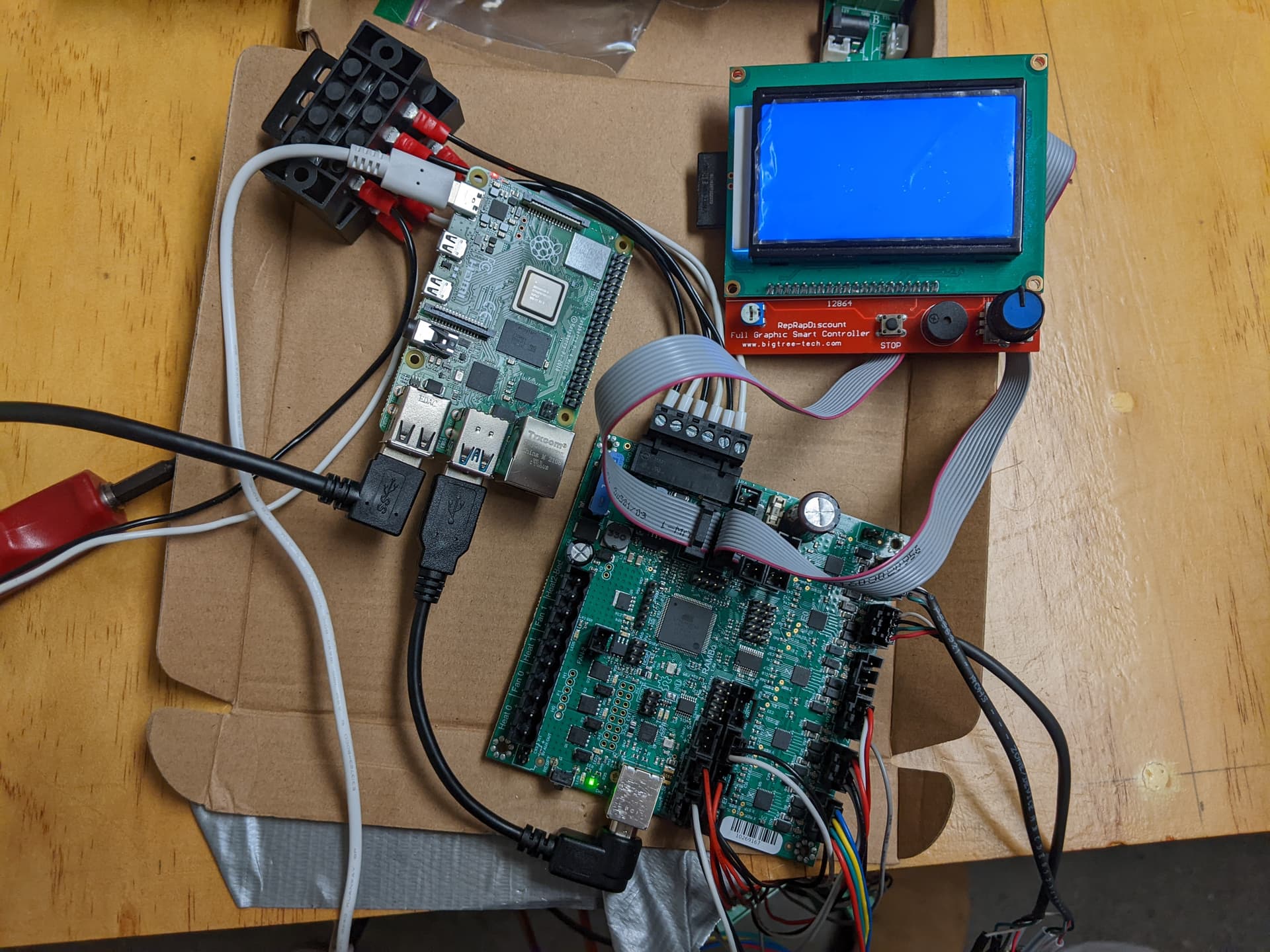
The LCD was working with this setup, but for some reason, it just started showing a blank blue screen. It has a number of always on white pixels. Maybe it went belly up. I bought it from Ryan over 5 years ago, and haven’t used it much.
It isn’t reversing anything internally, is it? You didn’t reverse any settings in cncjs? Once you get the screen, jog Z up and down there to make sure the direction is right.
The screen will be blank if it is wired in backwards. If you didn’t change the wiring, it might have been pushed in too much.
The firmware looks right. The output from M119 looks right. If it is going the wrong way, that usually means it either the endstops are triggered, or the Z steppers are going the wrong direction. Not sure what else can cause that.
I think we are saying the same thing. In the cncjs, I set the jog amount to 5mm and then press Z+ and Z-. Did I say that correctly? So the DualLR firmware, as is, is set up for Zmax, and it should move upward, with increasing Z values, when homing? The only setting changed was from software endstops to hardware endstops. Isn’t that necessary with limit switches?
On the LCD, if I flip the connectors, it is unlit. As wired, it is lit blue, but blank. I thought it might be that it was plugged into the Raspberry Pi running cncjs, but after shutting down, pulling the USB connector and rebooting, the screen was still blue/blank. I could try it again with the Mini-Rambo, which it was also working with in the last week.
The screen cables can also be rotated 180. That can also lead to the screen being blank.
Some gcode senders can reverse the jog buttons. So +Z might be G0 Z5, or it might be G0 Z-5. I can’t remember if cncjs has that feature. But toggling the direction of the Z button in cncjs isn’t going to change it in the firmware. So if you had to change that setting in cncjs to get the motors to turn the right way, then you have to undo that change, and fix the root cause in the firmware (the easiest way is just reversing the stepper motor connections to reverse their direction).
I might order another from Ryan, along with some spare couplers. I just checked mine and they seem fine, but the Z-Axis has just started making an odd stuttering noise, it was smooth a few days ago. Perhaps I will take a break and revisit this next weekend. Thank you very much for all the suggestions. You are amazing helping everyone. I only got this far reading all the posts where you helped other people.
I found this pen holder and will try the test crown. I had not thought to run a drawing test until all the axes were working correctly. I was going to draw a rectangle at that point to check the squareness of my Y-endstops. Will post the results. Again, thank you.
@jeffeb3 I tried the test crown. The pen holder was very wiggly, so the drawing was crown-like, if you knew what you were trying for. That’s probably good enough, but I found/printed another pen holder. Unfortunately, it slides through, so I will add some duct tape and hopefully, it will clamp down.
On the Z-axis problem, the system homed Z ONCE correctly. I was ecstatic. However, when I tried this morning, the left Z stepper homed down instead of up, the right did not move, and I quickly unplugged it. What might cause that behavior? If the wiring on the right Z stepper was intermittent, would the firmware decide to home downward on the left?
Once the endstop is triggered, it will back away from it 5mm and then go back in more slowly (to get an accurate measurement). If it is already triggered, it may go the wrong way to back away. But I can’t explain why it is different on the other side, or from the other day. Software/firmware doesn’t wear out. So it must be something electrical.
So… more weirdness and maybe a clue you will understand as to what is going on. Over the years, I’ve bought 2 Rambos (a 1.4a and 1.3L) and a MiniRambo from Ryan, so I hooked up the MiniRambo. I moved just the right Z-stepper, that had not been moving, to the MiniRambo and using the cncjs job it moved, but in the wrong direction. So I flipped the 4 pin stepper connector… and it moved the same way - wrong direction. That is weird. Is there a way you can miss-wire a stepper to get that behavior? So I moved the right stepper back to the Rambo and moved the left Z-stepper, that had been moving, to the MiniRambo. It too moved in the wrong direction, and when I flipped its connector, it too moved in the same wrong direction. What the frack did I do?
On the Smart Board LCD, moved over to the MiniRambo, which worked several weeks ago, it just showed a blank blue display. Perhaps it finally died. I will order another. Thank you again.
I think the Rambo 1.3L is running non-Dual firmware, so I can probably test both the LCD and steppers with it too.
It is fixed and now homing on all axes. I chatted with a very savvy CNC friend and he didn’t know what it was. It shouldn’t have been doing what it was doing, even with incorrect or bad wiring. I suspected the wiring as the Dupont connectors were not happy with 18 gauge solid wire. So I cut off all the Dupont connectors and soldered/heat shrinked all the connections. I didn’t want to wait a week for different connectors. It works!!! The Z-axis limit switches are now calibrated and square. I am going to try the crown with a different pen holder. Thank you for all help both here and elsewhere.