Hi All,
I was recently donated a LR2/Mini-Rambo 1.3a kit and have it basically working with single end stops.
I need to rebuild the firmware so I can set the table size properly and during that process I started digging through the documentation which is dangerous due to my background.
It appears that my board does not contain enough drivers to perform dual end stop homing so I have designed a Serial Stepper Multiplexer board which should let me disable each stepper individually.
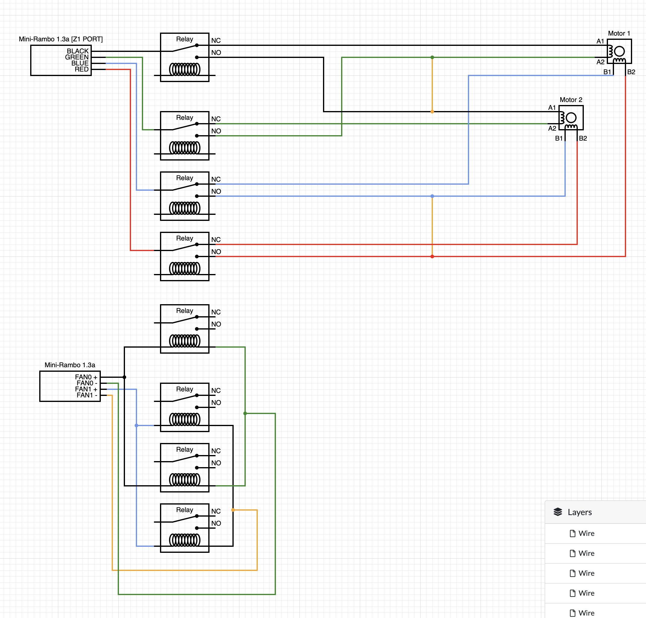
The default state of the board is to have 2 motors connected in series, to the input, the A and B pin pairs are directly connected to the relays, when 5VDC is applied then one of the motors will be disabled by having both of its coils disconnected.
My first prototype boards will be arriving in about 2 weeks and If this works well I will look into a third revision which includes hardware debouncing for the ends stops and some straight through connectors for a third probe/end-stop to assist with cable management, and another to allow for an external Z-Probe attached to the board (again, Optional assistance for cable management. )
I hope that the 2 FAN PWM outputs can provide enough voltage to trigger some HK19F-5V relays or if I can find a nice source of “4 cleanly grouped outputs” which could trigger said relays.
My plan is to:
0) Wire my new splitter to the z-axis.
-
Add a new compiler flag “P0_Z_AXIS_DUAL_ENDSTOP” / “ aka Power Off Z Axis Dual Endstop
-
have most of the the DUAL_ENDSTOP code enabled with this flag except making sure that we are only controlling a single stepper motor for Z. ( Future research is needed to figure out what is needed how to make a P0_Y_AXIS… compiler define and keep the “E Axis” free so it can be used as a Y2 )
-
during the G28 Homing cycle when a “Z” end stop is hit:
3.1) hold the reset pin on the Z Stepper driver.
3.2) Toggle ctrl pins on new board to determine which Z motor’s end stop was hit and then disable that motor. (if both end stops are hit at the same time then skip to 3.4)
3.3) continue homing until the other Z end stop was hit
3.4) toggle both motors as needed / drive forward/back to apply M666 offsets.
3.5) enable both motors, return to normal machine operation -
write glue required so the Z-Max ends top actually works ( since Z-Min is now multiplexed. )
so some questions for the community:
-
will the EMERGENCY_PARSER directive work with the mini Rambo ?
-
does anyone know how to enable max endstops in marlin ?
-
Is there a definitive list of settings for configuring the marlin for the mini Rambo board to control the LR2 ?
-
are there any spare pins which I can utilize to trigger relays without loosing GPIO functionality ( currently I only have the fan pins, I read somewhere that some of the end stop pins can be utilized as a PWM.
-
Can anyone please poke holes in my design ?