LowRider Z Leveling Math

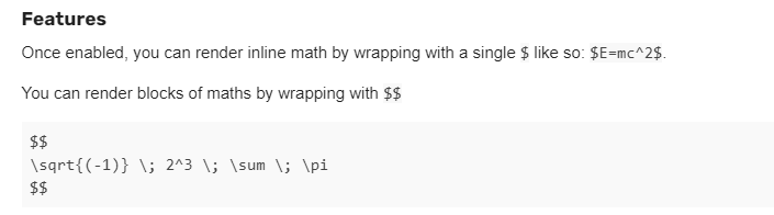
If you don’t like math, you should stop reading now. :laughing:

I’m working on an extension to the FluidNC UI v3 to automate z leveling but this calculation applies more broadly. I think I’m chasing zeroes a bit but could use some help.

The current instructions for figuring out the values are a bit of an educated guess and check, and that is sufficient, but I’m looking to do the math.

a = Difference between Z probe values between the left and right X locations
b = Difference between left and right probe X locations

It’s kinda like b is the spoilboard, c is the gantry-ish, and a is the offset.

You can’t just take a and use that for your offset because you need to consider the full X width, so it’s going to be larger.

So, you can find the hypotenuse c and \angle{A} in radians:
c=\sqrt{a^{2} + b^{2}}
\angle{A}=\arcsin{\frac{a}{c}}

If you then re-calculate the height using \angle{A} for the full width, it should give you the right value.
If you have the full triangle as d/e/f similar to a/b/c, you have:
e = full width
\angle{D}=\angle{A}
f=\frac{e}{\cos{\angle{D}}}

Ultimately, we want to find d.
d=\sqrt{f^{2} - e^{2}}

If I’m correct to this point, my real question is, what is that full width to use in the calculation?

  • Lead screw to lead screw? This is my guess but I was overshooting the value a bit.
  • XZ plate to XZ plate?
  • YZ plate to YZ plate?
  • Left bearing to middle of Y rail?

Javascript function for reference:

function getZOffsetChange(xDistance, xTotalDistance, zDistance) {
    // Calculate angle
    var a = zDistance;
    var b = xDistance;
    var c = Math.sqrt(Math.pow(a, 2) + Math.pow(b, 2));
    var angleARad = Math.asin(a/c);

    // Extrapolate over full distance
    var angleDRad = angleARad;
    var e = xTotalDistance;
    var f = e / Math.cos(angleDRad);
    var d = Math.sqrt(Math.pow(f, 2) - Math.pow(e, 2));

    // Keep 3 decimal places
    return +d.toFixed(3);
}

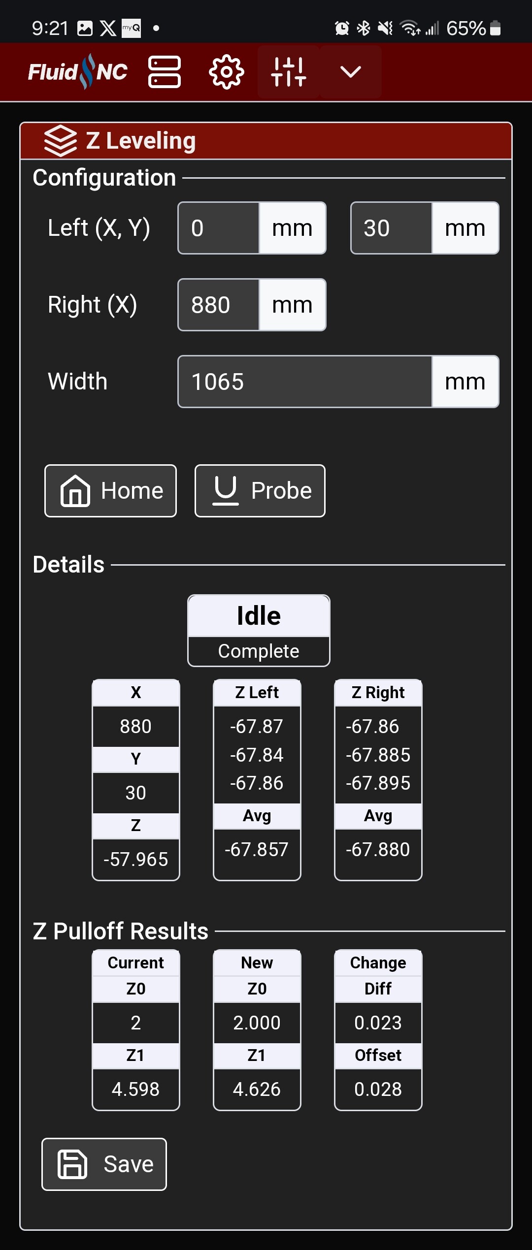
Here’s what my extension looks like at the moment. There are some hardcoded numbers I need to parameterize (860mm between probing values, don’t remember which total width I was using). This was after I ran it the first time and set the values, and then ran it again to see how far off it was. Either way, 0.2mm is tiny.

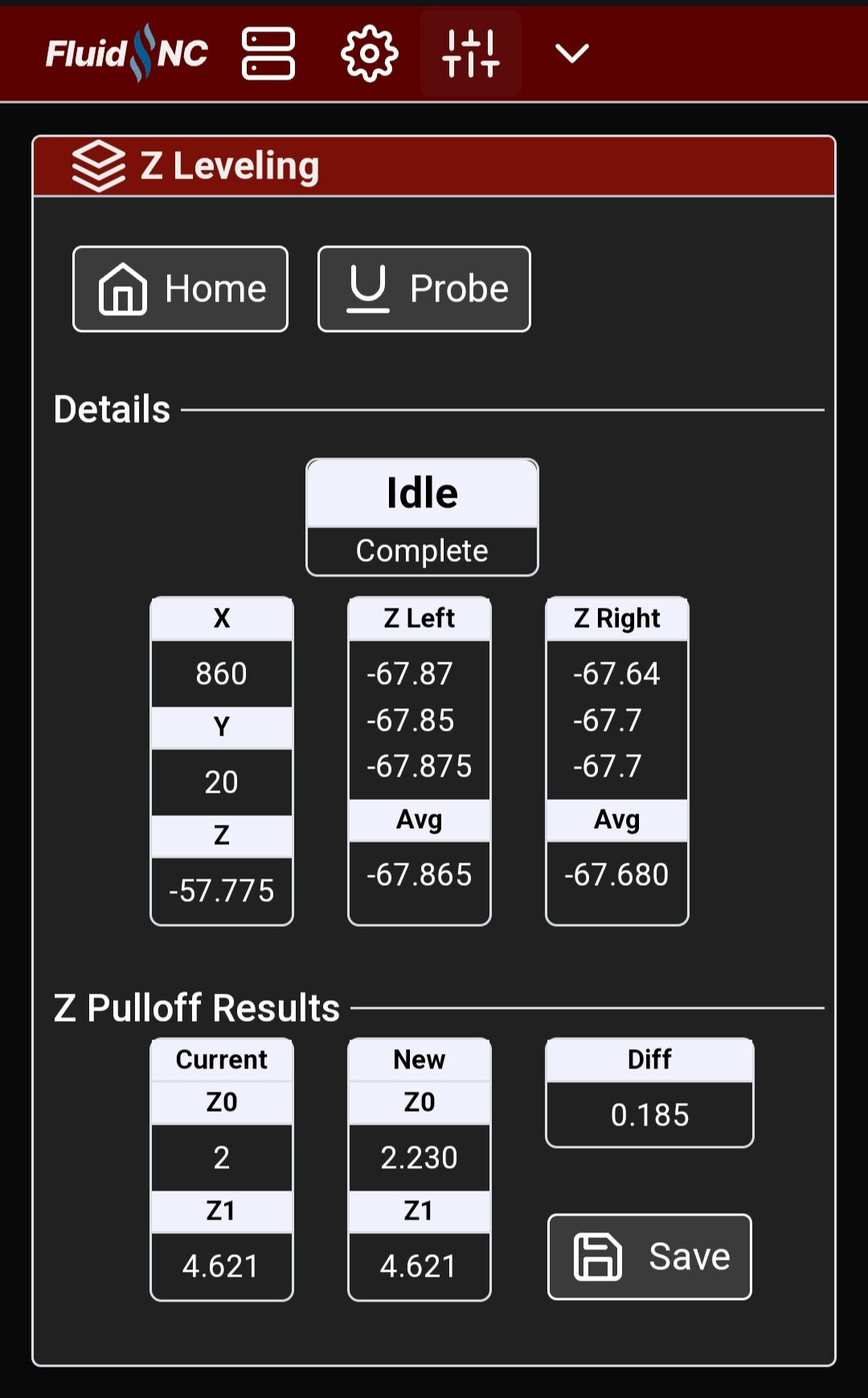
Functionally, you click the Home button to home all axes. Then click the Probe button, which jogs to a starting X,Y location (currently hardcoded to 0,20 for me), starts the probe, once it returns to idle stores the Z position and jogs Z up, repeats the probing 2 more times, moves to the right position (currently hardcoded to 860,20 for me) and repeats the probing. When it’s done, it calculates the results and you click save to update the values and save. So, you do that all by clicking 3 buttons and holding the touch plate for 6 probes.

5 Likes

I am pretty sure it is the center of the Rail, and the outside of the bearing depending on which way it is tilting (3.5mm difference if it is on edge of the bearing, center if it is real close).

But…the core is 180mm wide. 90mm on each side and then a probably 5-10 after that. At zero and X max that ±95-100mm is going to get you extremely close to the real number, (the X endstop position complicates this) The wider the machine the closer you are.

I did this in CAD a few times, the numbers are very very close. I think someone else made a calculator for this, Dan maybe.

If you are 0.015mm off currently, what did you use for the full distance? (those 3x probes are way more consistent than I thought we could get).

1 Like

PS…this is super RAD.

3 Likes

I’ll give that a try.

I tried a bunch of different things and I lost track. I’ll sort that out tomorrow. It was 0.185 off, which translated to a pulloff change of 0.230.

I’ve been doing a lot of probing and I’ve gotten more consistent. Having it auto-record consecutively like that makes it easy to see how variations in pressure affect the values.

1 Like

Ok this is cool!! I made excel spreadsheet that I print out before I check mine and I thought that was handy. But this is another level here!! Watching closely!!!

2 Likes

That looks great!

2 Likes

For the total width, I ended up using the distance between the inside of the left bearing and the middle of the right inside bearing where it touches the Y rail (1065mm). When I used the outside of the left bearing to the middle of the Y rail (1080mm), it was overshooting the calculated offset by a small amount, but less than where I landed. Technically, my new value was slightly under, so maybe use the center of the left bearing?

Either way, in one shot, I can’t argue with this. This is performing the leveling and then running it again to see how close it is.

Here’s an 8 minute video if you’re suffering from insomnia.

4 Likes

The Y rail to the opposite side wheels, I think, as that is where the interactiion between the gantry and the spoilboard takes place.

I used that for my calculations.

My adjustment was taking the difference in probe values, multiplying by the distance from rail to wheels, and dividing by the distance between probes. That is to say, extrapolating the distance between probes as a percentage of the adjustment. I don’t find out what angle the gantry was at, but I don’t care, I just want the adjustment factor.

2 Likes

Yes!!!

1 Like

I just realized I’m talking about being within 1/1000 of an inch. We’re surely beyond what we can accurately measure. This means using what you suggest, which is the same as Ryan, is still absurdly close.

Ohhh, that makes so much sense! It gets the same answer but is way simpler. I went down the geometry path trying to make sense of it. I clearly wandered too far into the weeds.

\frac{probeZDifference}{xDistance} = \frac{x}{totalWidth}

x=\frac{probeDifference}{xDistance} * totalWidth

2 Likes

Okay, I’m not going nuts, that makes me feel better! When I saw the first post, I thought, I must be missing something, that math seemed way more complicated than necessary, I thought. we’re just dealing with similar triangles \frac{d}{a}=\frac{e}{b}=\frac{f}{c} so, what’s up with Pythagoras and the trig?

BTW, how do you include math symbols in a post? Edit: Thanks to Mike M for introducing me to mathjax

1 Like

MathJax

$E=mc^2$

E=mc^2

$$
\sqrt{(-1)} \; 2^3 \; \sum \; \pi
$$
\sqrt{(-1)} \; 2^3 \; \sum \; \pi
4 Likes

Thanks, I’ll check that out when I’ve got more time.

1 Like

I have a friend with a PhD in Math, who hates people calling arithmetic “math”… so of course I do it even though I get the difference. He also really hates engineering math that uses some admittedly ridiculous shortcuts to get answers that work well enough in the real world, so I’m sure to throw some of those in once in a while.

In return he throws Hollywood tropes about stuff like martial arts my way. I try not to let thst set me off :rofl:

1 Like

I remember one of my very last math classes, “neglect the resistance of air on this projectile” I kept thinking “at what point in the next two weeks are they going to tell us how to account for air…??” Every single class had stuff like that. They always seem to leave out the important stuff.

2 Likes