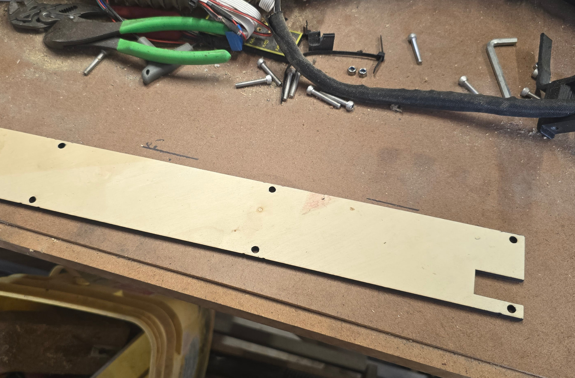
on a whim, I decided to cut section of the new size strut plate on the laser. Glad I did. The holes are not quite the same. I looked at it twice and couldn’t tell why the holes weren’t lining up. Turns out I need the laser version as a template instead of my old strut plates or the holes won’t be evenly spaced. Then i was thinking it would be better to cut two plates with the laser out this ¼” ply and using the machine with a drill bit to make my holes in the new steel plates. 10,000 rpm is the lowest my router goes though, and I’m not sure what my bits will do at that speed, but I know i don’t want to find out. I even thought briefly about how to redneck engineer my plasma cutter torch onto the gantry. But there is so much wrong with that its not even funny. So im back to my original transfer punch idea with the new laser cut section as my guide instead of the old strut plates. I have enough experience with that kind of work that I am fully confident I can do it without any issues.
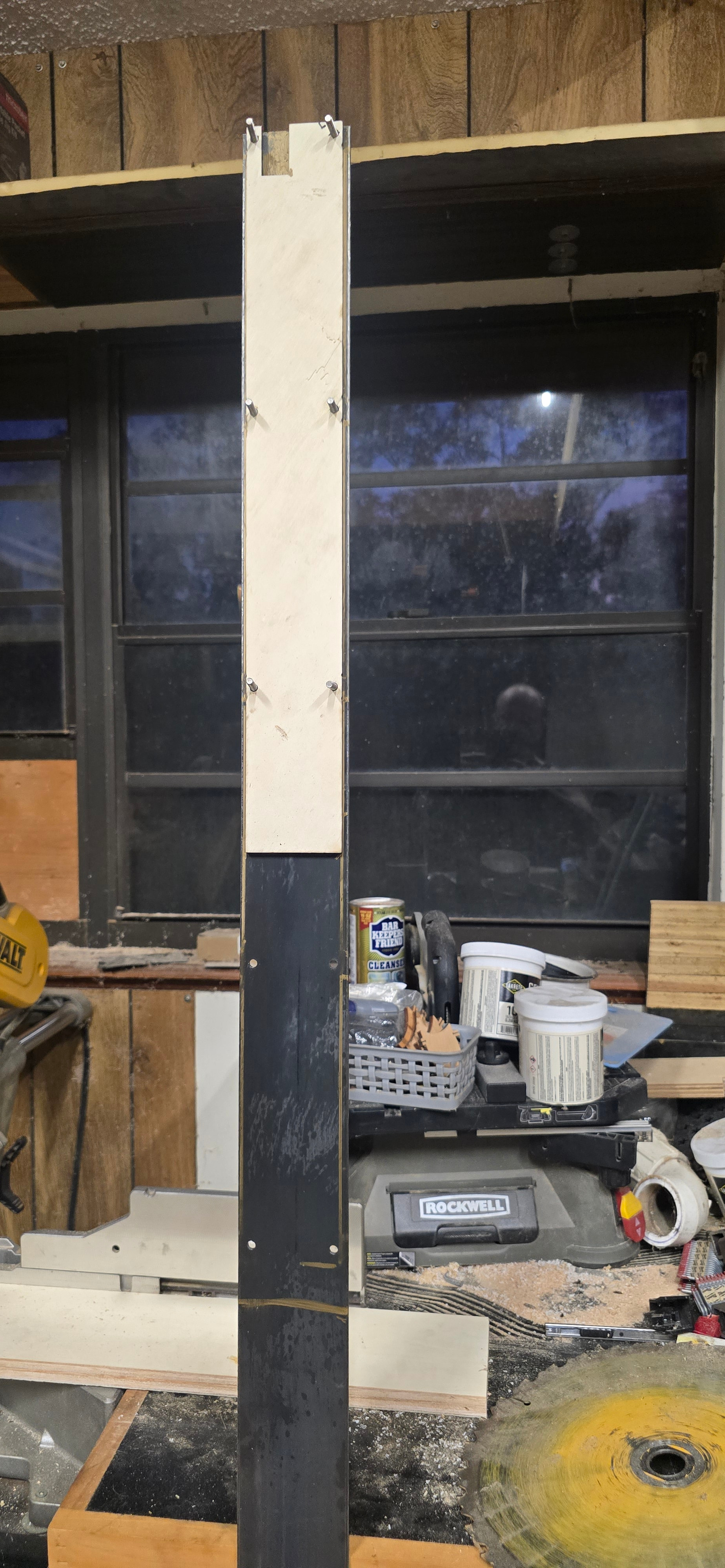
PSA
THIS IS NOT YELLOW BRICK ROAD STANDARD REQUIREMENTS
I got to mockig up the laser cut section, and then got carried away. I now have all the holes drilled for one of the strut plates. I was referencing holes off each other like beg board and moving my part right along. I completely agree this is not for the general maker who just has a few general tools. That being said, if you have the right tools skills AND experience, it’s not a hard job. Just have to be methodical about it.
There is a note on the build instructions about ti l the tube’s not going past the last strut braces. Then troubleshooting here on the forum, that comes up a lot as well.
Has an end cap ever been considered? 3d printed end cap that has all the same holes for wires and screws, but caps the tube’s and plates. Could even build out little plugs of sorts that go into the tube’s to help reference them… though the strut brace really does most of that.
The LR4 is a great machine because everyone, with a 3D printer and basic tools, can build with good results. On my two LR’s I have aluminum strut plates, but after basic load test I found that the difference is not that much.
Anyway, In my opinion the idea of heavily modify a LR with metal part when the core is still a 3D printed part is wrong. If You want a CNC to cut metal go with a full metal one, like the PrintNC.
For cutting steel plates probably a Plasma would be better. For aluminum plates milling, a smaller LR4 is ok. But if You intend to mill more complex “3d parts” out of metal the lowrider is not the right machine: the moving gantry is its strength, but also his limit, cause You loose the clearance that a standard machine has. For example: clamping, the core is always too close to the workpiece surface that a bigger clamping is almost impossible.
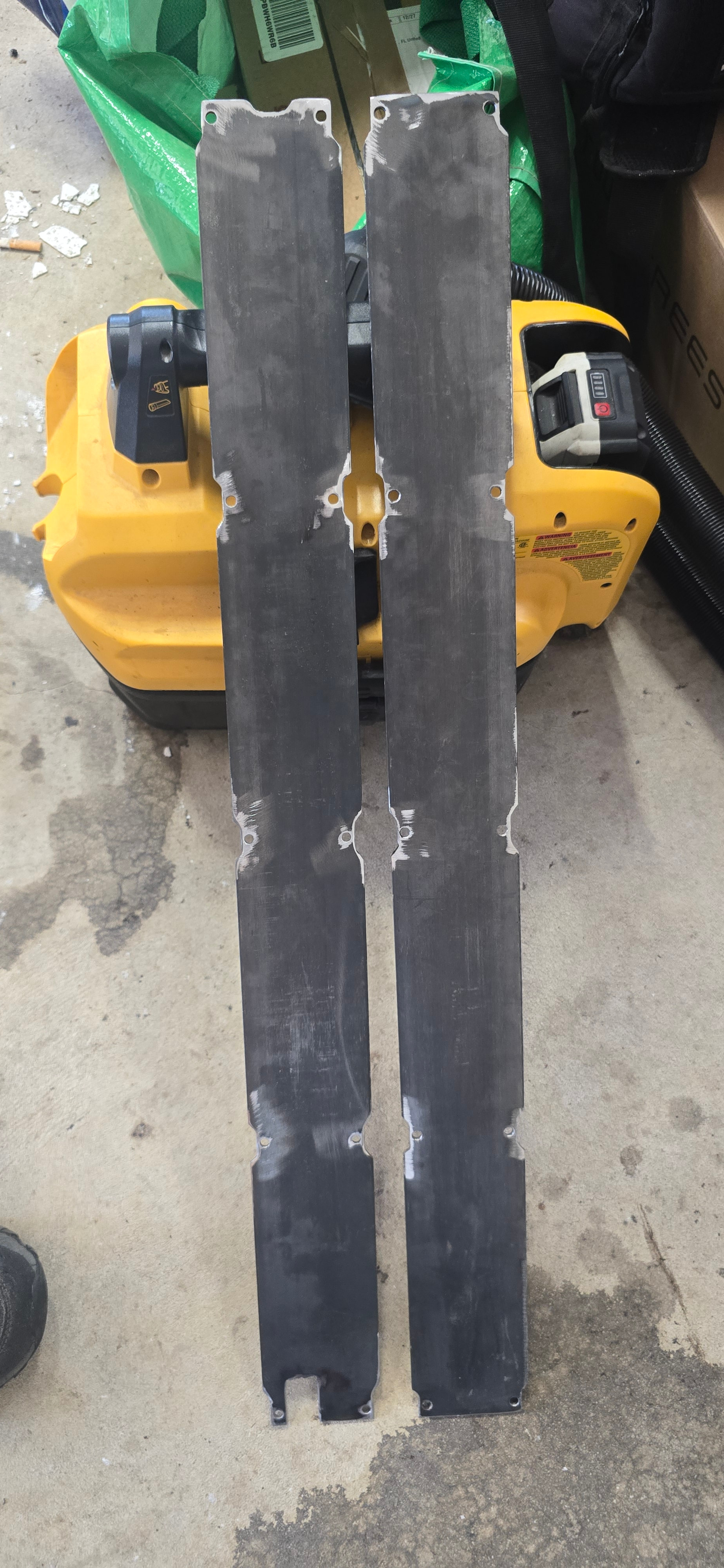
I took a journalism class forever ago and one the things I actually remember is to not state opinions as fact. I am in no way discrediting your experience or opinion. I even agree with lots of the things you said. But I wouldn’t say it’s wrong. The end use really is the important factor. If you start at the top and look what Ryan and the team are designing for, it’s arguable that it is one of better machines on the “market.” Then you start looking at how guys with experience with them start to change this that or the other, they aren’t designing to the same criteria as v1e. They have a much more specific use case In mind. For that reason alone, you can’t really say that its wrong. That’s like saying to a guy who wants a faster truck that he should just get a corvette. He would lose the truck abilities. Yes the vette is objectively better at going fast, but it would not suit that guy’s truck needs.
Now…… I agree on the z being the double edged sword. It’s much better down low because the whole gantry supports it. But up high where facing a metal piece would likely happen, is where it’s at is weakest. And there isn’t as much z travel as some of the other options which can be a very limiting factor. But at the end of the day, I can’t afford a big enough hunk of aluminum to to max out the z on this and any attempt at getting the machine to do it would be a waste because I don’t have the need for it.
I also agree the core remains a weakness in harder use case. Not because of 3d printing, but because of the architecture. The bearings on the emt can only hold so much tolerance. Even with preloading and being as picky as humanly possible, they are Chinese bearings on tube that really has no set tolerance for this use. I have no example in any observation that the printed part even thinks of flexing. If i did, that’s easy to fix in the slicer and filament choice. Everything I have seen is the core moving on the gantry and the gantry twisting under extreme load. My opinion is that the twisting is the plates, and the cure moving is the tube. My current plates i can twist by hand. If the plates themselves are harder to twist, then they should lock the strut braces in plane better. If the tube is held to tighter tolerance, you can get the bearings adjusted better. I don’t think any of this will be a magic wand, but at the cost of my time tinkering in the shop and some material I have in stock already I’m willing to test it. I’ll never be able to cnc a new set of heads for example, but I’m pretty sure I can machine an alternator bracket..
Thank you for weighing in with your thoughts. I didn’t ask people to agree with me. I asked for their t thoughts and experience. Yours is as valuable to me as any other. I think the fact you have two low riders proves you aren’t bashing the machine, but rather pointing out what you see as a limitation. That is exactly what this community is for.
Thinking some more about the end cap idea. The z axis is two linear bearings bolted to an aluminum plate. Then the gantry bolts to that. If there were aluminum end plates on the gantry itself, then you go from aluminum xz to aluminum gantry interface. You could i guess just make the xz plates taller so the tube’s dead end at the plate in a controlled manner. But without being able to ensure that every builder is cutting their tubes perfectly, I guess an intentional air gap prevents the type of pushing the sides out of square that normally becomes the trouble shooting journey I have seen on here.
I’m just thinking out loud at this point. I know lr5 design is churning in the background.
I found that rather than try to get the X axis tubes “perfect”, I just cut them ~3mm shy of ideal, then you can be reasonably sure when all is said and done that you can install them into the braces so that no end of either tube is pround of the braces at the ends. That seems like the easiest way to me…
I had it in my head that I’d eventually replace the MDF painted in tightbond on one of my LR4s with some aluminum strut plates. That was until I put together a fully printed beam with printed strut plates in segments and additional braces instead of interlocking plate segments. That beam is really stout.
My guess is to really get the benefit from metal strut plates, you’d need to use more braces…
Again, machine optimization is hard because Ryan did such a good job in the first place. There are no low hanging fruit to pick.
Funny thing is that i have never has an issue with mine. I was just thinking while working and this seems like an easy issue to deal with. It’s also is a non issue.
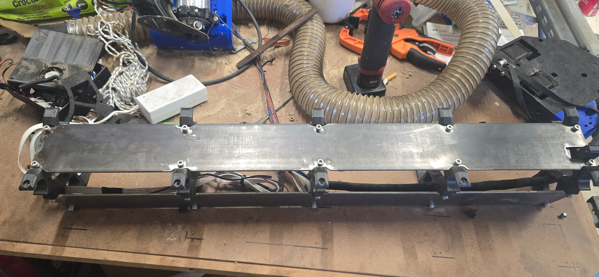
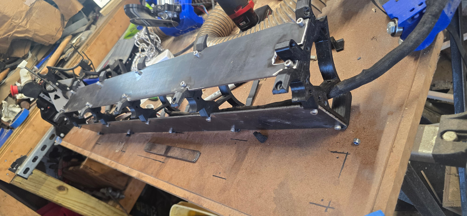
Dry fit up is a success. I guess the hard part is over. I’m going to cut and install the emt for now, but i really want to see what I can find kicking around locally.
I see it the other way around, but i may be way off. I think the metal not wanting to bend or twist lessens the need for more braces. I think if you printed one long gantry the exact same as the braces but it spans the entire length, that’s the idea. The plates are just trying to hold the struts in alignment without the need for an 800mm z axis printer. Paper would twist with the brackets almost touching. That stuff they made wolverines claws from would never twist even if you only had braces on the very end. The goal is to get the alignment as locked in a possible without adamantium. The screws pulling on the plates and the braces plays a role. The tube being clamped by the she bolts holding the plates plays a role. The location of the core when it’s applying these forces plays a role. That’s why I think stiffer plates have historical only done better to a certain point. After the plate resists the forces enough, the weaker links in the chain start to show up instead of the plate itself. But these are just my thoughts on wheat is happening. I have no actual facts other than my steel plates fit.
An interesting idea would be to replace a strut with a torsion box and see what happens. But that’s above my pay grade.
@MakerJim, I just want to clarify what I said.
I think we are thinking the same things but from two different angels. The longer the span between the braces the more room for torsional distortion…. Period. More braces shortens that unsupported span. Period. Stiffer materials can span longer sections without needing more support. Period. Those are all facts. The question in play isnt any of those things. It’s how do we realistically get the most rigid gantry that resists the torque without costing a fortune or weighing a ton. I’m pretty sure more braces has proven itself many times. Aluminum has proven itself as well, but there is some question as to how much. I’m sure if we set up 5 machines with only 1 thing different on each we could narrow down the amount of change from each aspect, but pulling data from several machines with different variables gets more daunting.
Right.
Only true if the braces have extra margin. They don’t. It’s an optimized system.
I was speaking in general terms. And yes I agree there is a limit.
So the newest random thought is the width and interface of the plate to brace. I think these braces are something like ¾” or so. What would happen if they were 1½” with 4 bolt locations? I would guess not much if anything. But it’s the new random thought. I think this would help a ton IF the issue was the plate and brace trying to rack on each other. But that’s not an issue i would suspect with this. I’m really just typing the adhd thought train while I work. I think half of my ideas are just not worth testing and the other half probably have been tested already and found to not help.
I didn’t get pictures before taking everything back apart for paint… But the emt tubes are cut, and i had the whole gatntry ssembly together minus the belts.
I’ve been asking that same question a bunch lately.
The braces have nice chamfers at the top and bottom so it isn’t as simple as stacking two of them in a slicer. Well, I suppose you could, but then that stacked chamfer in the middle between the two halves would trigger my OCD.
The other question is the screw holes into the emt. I thought i heard it was something that could cause more harm than good if not done correctly. But what did the testing show for possible gains? Seems to make sense that they would help. The brace has that much more grip on the tube meaning the tube is helping with the torsion. I can also see how if they aren’t exactly right, that tube is now a torsion bar complete with preload.
Demonstrated.
Several tested it. Most had worse performance because it turns out that it’s hard to get the screw holes correctly aligned and drilled and if not precise it is a big step in the wrong direction. I think Ryan did some more testing and ultimately we all gave up on it. Interesting idea, not practical. Hopefully Ryan comments more on that.
Of all the things I have checked. The collet to the lower rail show no measurable movement under normal loads.
The Rails do not touch the strut plates, the braces do. So if you have an infinitely rigid strut plate, then you are fighting brace flex. More braces, less flex.
The strut plates are only connected with screws. So any slop in the screw holes also equals less rigidity transfer.
You have to be careful with the line of thinking you are on. You are thinking ideal materials, similar to how inmath exams they always say “assume air resistance (or friction) is negligible”. The small things can, and usually do, sometimes add up to larger things.
extremly small factor, how much can an unsupported emt rail hold at 300mm, now divide our load by 4 points of contact.
Then you rely on the braces less than the strut plates on the current design. There is a way you can tuck a brack more under the strut plate but that should only help in one load direction, not the other.
If you look at the current design, do you guess it is stronger while moving in Y+ or Y-? It is far stronger in one direction but has nothing to do with the beam.
Since this is a brainstorming dump… I’ll offer
- What if instead of the screw penetrating the tube, it clamped the brace tighter to it? kind of like the core clamps the EMT “rail” to get the bearings to touch, have the braces clamp the EMT as well
- Maybe some friction between the emt and the clamp would be helpful like some thin doublestick tape or epoxy them in place.
- Perhaps make aluminum braces and attach them similarly as #2 or use a printed alignment jig before attaching to ensure alignment (likely compounding issues with that one).
Sneaky, Ryan, but if it is what I think it is… it does have something to do with the beam.
Hint: My guess is that if you make some triangles along the YZ plane with the point of the cutter head to one wheel on the YZ plates and the other wheel on the YZ plate you will find that the triangle asymmetry is instructive on how the system will react under load.
I’ll bet Ryan took into account which direction a typical trim router spins the cutter… Crafty. Very crafty.
Edit: Since the force reacts through the XZ plates, the correct 3rd point of the triangle probably isn’t the cutter, but rather close to the center of the lower tube on the beam.
Let me explain: I’m not an english speaker, so my ability to present my ideas is not the best, so my sentences are simple and straight forward.
I always used to be the “mod guy” my whole life. Nothing in my hands stays stock: cars, bikes, guns and also tools ..etc.. because If I can improve it, why not? I’m not against Your spirit, I want to be clear. At the same time I realize that, sometimes, things doesn’t need more strength or power, only need more balance. Modifying a truck to be faster it’s ok, but if You make it too fast to be stable It need lower and more rigid suspension, that are worst for “truck things”.
I dont know why but this is what brain needed to hear. Like a common sense brick hitting my upside my head. It doesnt change how I see the function of the plates, or the importance of them. But it paints the picture of what the testing has shown the issue to be.
this (very simplified) is saying that the emt deflects between the braces….. atleast thats what I heard.
So in imaginary land:
the strut plates and screws are perfectly attached to perfect strut braces. The tq of the mil is bending the emt . The (impossibly so) perfect plates and braces, limit that bending to where its unsupported. As unsupported section get smaller, the amount the emt can flex gets smaller, and under the same loads deviation is reduced? Adding additional braces (still imaginary and perfect) to half the distance, make the tube something like (2)^3 stronger.
Now if we take that same thing but remove it from the vacuum of imaginary land and things change, but the theory doesn’t.
The plates and twist, the screws have room to move, the braces are not rigid mounted to the emt. So the emt bends between braces, but can pull the next brace ever so slightly out of alignment allowing for the next span to also bend
I feel like Im about to get schooled on this one….. but I welcome it.
the core mounts on the Y- side. as it moves Y+ its pushing the mil backward and the top to the core is pushed against the top rail. Meaning the triangle is offset to fight against the tq of Y+. So it would be stronger in the Y+ and weaker in Y- not because of the beam but because of the side of the beam its on. I would also assume that is why the gantry bolts off-center to the xz plates so the moment arm gets centered on the aluminum XZ.