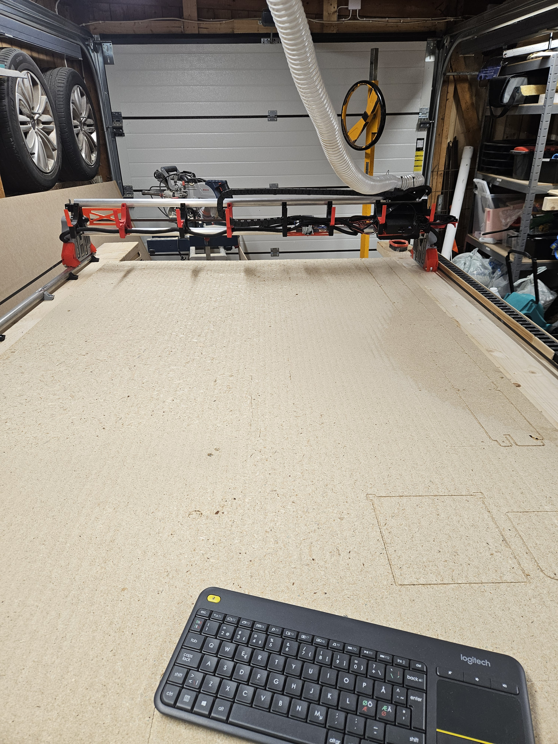
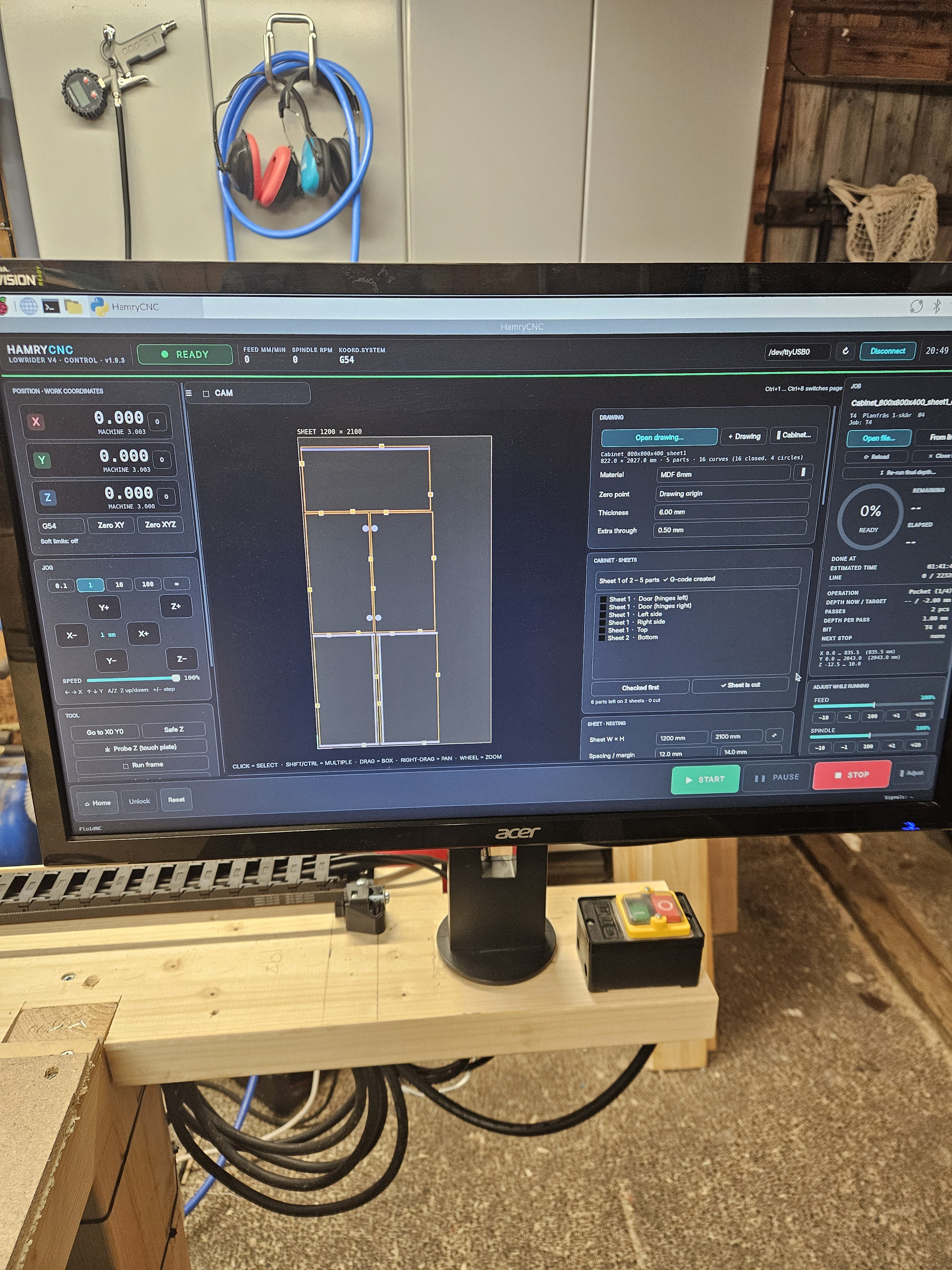
My LowRider v4 build is almost finished, with just a few small things left to sort out. Alongside the build I’ve been working on a control program for it (Jackpot board / FluidNC, KATSU 710W router). It runs on a Raspberry Pi 3 with a screen, mouse and keyboard right next to the machine. I wanted one place to do everything from drawing to finished part, without moving between a PC and the machine.
Pocketing that plans like real CAM (far fewer retracts), plus adaptive clearing
Arc output (G2/G3) and feed adaptation (chip thinning)
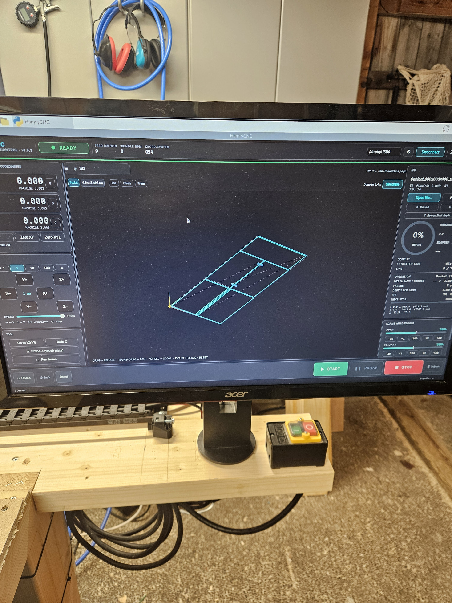
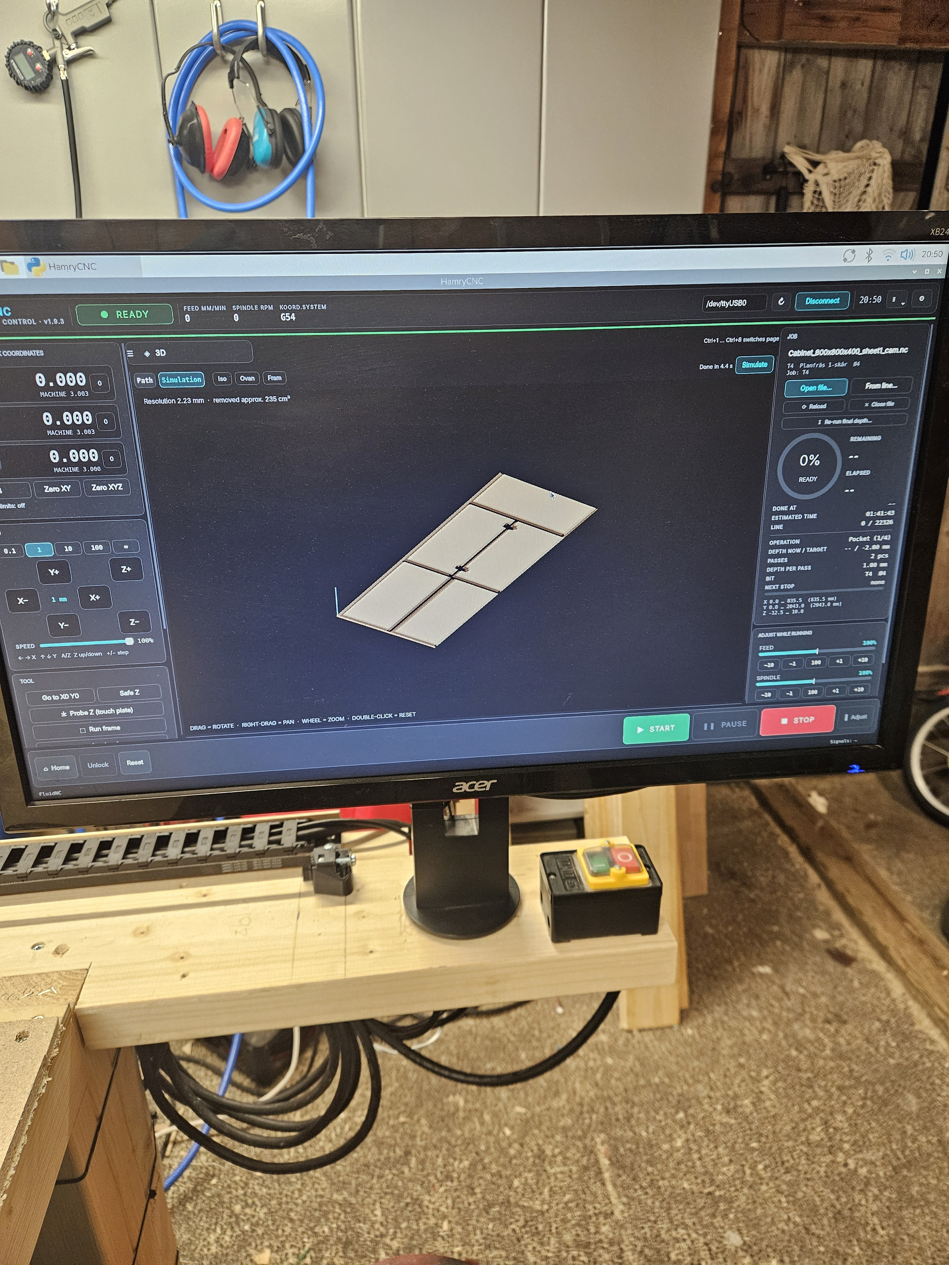
Nesting on the sheet, cut lists and job cost estimates
“Re-run final depth” if a cut didn’t go all the way through
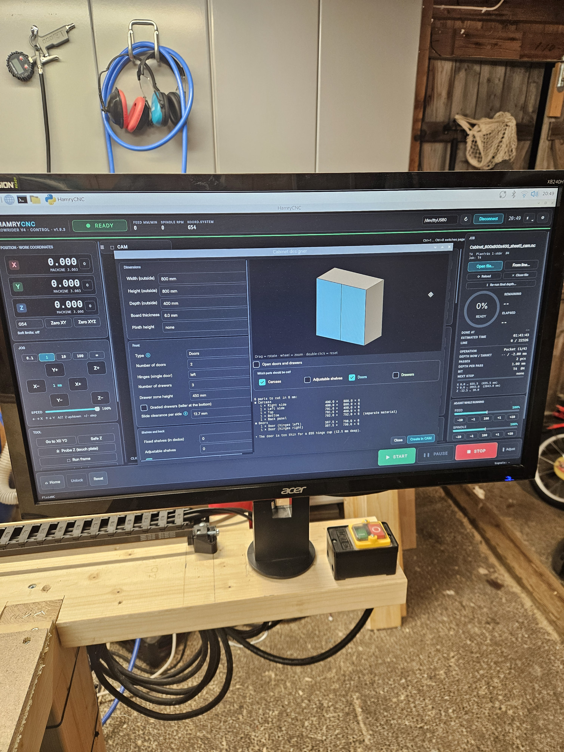
Cabinet designer
Enter the cabinet’s width/height/depth and get every part with dados, back groove, System 32 shelf holes, 35 mm hinge cups and drawers
See the cabinet as a rotatable 3D model before cutting
Choose which parts to cut (carcass, shelves, doors, drawers) and which sheet to run first
Extras
Part labels with QR codes (Dymo) and a sheet label with layout and cut list (4×6" thermal printer)
A web page for sending files from your PC, and phone monitoring with pause/stop and push notifications (ntfy)
Swedish and English UI
It’s a personal hobby project, not a commercial product. Most of it has been tested on a simulator and some in the machine. Once the last bits of the build are done I’ll test everything on the real machine and post updates and pictures here. I’d love to hear what features you’d find useful, or what you use today for running your LowRider.
Welcome! The test-cut calibration sounds really useful. When it works out gantry squareness from the four holes and the slot, does it tell you how much to adjust, or does it correct for it in software? I’m also curious whether the Pi 3 keeps up with the 3D toolpath simulation on bigger jobs.
It does both, in a way. After you measure the four holes and the slot, it shows the squareness error in mm over the gantry width, and in degrees. Then it offers to fix it for you. It doesn’t fudge the toolpaths in software. Instead it corrects the machine itself by adjusting the homing pull-off on one of the Y motors in the FluidNC config. That way the gantry is physically square after every homing. If the change would push the pull-off too close to the switch, it moves it on the other motor instead.
I can also just read the numbers and adjust it by hand if i would like to.
As for the Pi 3: it’s fine for running the machine and streaming G-code. The heavy stuff is slow on bigger jobs, though. A full-sheet cabinet nest with the 3D preview and simulation can take a while to compute, and the 3D view isn’t very smooth.
My plan is to move to a small used mini PC, which should make that part much faster.
The plan with the mini PC is pretty simple. I’ll run the same “HamryCNC” software on it as on the Pi, so everything works and looks the same.
The Pi 3 handles normal use just fine, but I keep adding features. Things like pockets, nesting and the 3D preview need a lot more calculation.
The Pi 3 does manage them, but bigger jobs can take a few minutes to calculate. I looked at a Pi 4 or 5 too, but once you add a power supply, case and storage, the price is about the same as a used mini PC, and the mini PC is a lot faster. So I’m planning to switch at some point, but for now the Pi 3 works fine.
Adjusting the homing pull-off so the gantry is square after every homing is a really clean solution, much nicer than compensating in the toolpaths. The mini PC makes sense too. Are you planning to share HamryCNC at some point, or is it just for your own machine for now?
I’m not planning to share HamryCNC right now. It’s still very much in beta. I’m adding features and changing things almost daily, and parts of it are only tested on my own LowRider v4 with a Jackpot board. I don’t want to put something out there that might behave unexpectedly on someone else’s machine.
I might release it in the future, once it’s more stable and properly tested. If I do, I’ll post about it here. Happy to answer questions about how I’ve solved things in the meantime!
Makes sense to keep it in-house until it’s stable, especially with something that drives the machine. One thing I’m curious about from your test-cut calibration: how does it separate the real bit diameter from steps/mm error? Is that what the slot is for, comparing its width against the hole spacing?
No macros, it’s built into the control software running on the Pi. From my understanding macro can only run fixed commands. This needs to read the results, calculate, change settings and check again, so the software handles it.
I probe with a regular touch plate and the clip on the bit. Works in below steps
Jog to two opposite corners to set the area.
It goes to each corner. I then put the plate there, and it probes Z (fast, then slow).
If left and right differ, it changes the pulloff on one Z motor in FluidNC.
It re-homes and probes again until it’s level.
I’m also planning to install a CR Touch next to the router so the machine can probe the corners on its own, no plate to move around. Might be a bit overkill, but my LowRider sits on a table with wheels and I roll it around quite a bit. So it needs to be recalibrated now and then, and I’d like that to be as quick and easy as possible
For test-cut calibration the machine cuts four shallow holes in the corners of a rectangle and a short slot in the middle. I measure between the holes, X front and back, Y left and right, and both diagonals. I always measure from the same edge of each hole, so the bit diameter cancels out. Then I measure the slot width.
From that it calculates new steps/mm for X and Y, the squareness from the diagonals (fixed by changing the pulloff on one Y motor), and the real cutting diameter of the bit, which goes into the tool library. It shows the old and new values and only changes things when I confirm.
Measuring from the same edge of each hole is a neat trick, thanks for explaining. Do you cut the slot in one pass at full width? I’d guess a bit of deflection could make it come out a little wider than the bit really cuts.
The interface looks similar to FigUI, is that coincidence?
Apparently you can serve UIs from the jackpot SD card, so if your project executes in a browser and interfaces with the board via HTTP requests, you could pair it with any front-end hardware.
I hadn’t seen FigUI before, but yeah, it really does look similar! I’ve used AI to help with parts of the code and the design, so it may well have picked up the style from somewhere like that. It’s a Python/Qt app on a Pi talking USB serial to FluidNC on the Jackpot.
Daniel, since you asked what features people would find useful, I will take the nesting / cut list corner of your list. Disclosure first: I built a free browser cut list and nesting tool (CutYield), so that is the part I have opinions about and I am biased toward it. No link, this is about your project.
On the Pi 3 compute time. For cabinet parts, which are all rectangles, you do not need the slow polygon nester at all. A guillotine or skyline rectangle packer with 0/90° rotation runs in milliseconds even on a Pi, and only parts with curves need the true-shape path. Routing the two cases separately keeps the common case instant. If you keep the polygon nester for odd parts, a time budget the user picks (5, 15 or 60 s) with the best-so-far result shown beats an open-ended search on slow hardware, and it stops the “is it frozen?” moment.
Three things I would want from the cabinet designer + nester combo:
Grain per part, not per job. Sides, doors and drawer fronts on veneered ply or melamine usually want grain vertical; stretchers, shelves and drawer bottoms often do not care. Your cabinet designer already knows which part is which, so it can tag each one “grain locked” or “either way” and the nester gets real freedom on the don’t-care parts. Treating everything as fixed costs sheets; treating everything as rotatable gives you a door with sideways grain.
Part gap driven by the measured bit diameter. You already calculate the real cutting diameter in test-cut calibration. Feed it straight into the nesting gap (bit diameter plus a small margin for a full-depth cut) so the nest can never be tighter than the toolpath. Every nester that lets the user type the gap by hand eventually gets a 6 mm gap on a 6.35 mm bit.
Offcuts as stock. After the first cabinet, the second one should be able to start on the leftover from sheet 1. Keep a list of usable rectangles after each job (even just “anything over 150 × 300 mm”) and let the next nest try those before a fresh sheet. Your 4×6" sheet label with the layout and cut list is the perfect place to also print the offcut sizes, so the leftover that goes on the rack is already labeled.
Seriously complete piece of work for a hobby project. Measuring from the same edge of each hole so the bit diameter cancels is a trick worth stealing.



 Good to see more Swedes here.

 This needs to read the results, calculate, change settings and check again, so the software handles it.
