LowRider-inspired Foam Ripper

Ah, I see it now that you have mentioned it… They are in CM and MM. So the move is ‘about 1cm’ not ‘about 1in’. :slight_smile:

1 Like

You could make a shrink ruler!

“A contraction rule is made having larger divisions than standard measures to allow for shrinkage of a metal casting. They may also be known as a shrinkage or shrink rule.”

Of course, if you make one, that will be the only one you can find when you need a ruler.

I personally believe it’s only right and proper to try making a ruler with these slick machines we’re building. It’s very satisfying to see them match up quite nicely with a commercial ruler. I put it right up there with the “MPCNC crown” :wink:

1 Like

Any reason your using 2.5W and not something stronger? Im not sure what the biggest laser module is that you can use in this application without mirrors, but I’m really interested to know what’s possible.

I’ve actually been using 3.5 watt Banggood lasers for a couple of years… and before that I had a couple of lower-powered lasers; i.e. a 2 watt unit and later a 2.7 watt IIRC. Repeating what I said a few posts above, about the smaller spot size of the lower-powered lasers, “… I was a bit surprised, several years ago, to find that my first 3.5 watt lasers didn’t seem any more ‘powerful’ than the 2 and 2.7 watt laser I’d played with previously… so I’m pretty sure its a “power density” thing; i.e. 2.5 watts concentrated in a ‘unit area’ is more ‘powerful’ than 3.5 watts spread over 4X that ‘unit area’.”

I was doing these tests over two years ago and had just starting to play with air-assist…

https://forum.flitetest.com/index.php?threads/cutting-foam-sheets-with-a-needle.24251/page-43#post-321202

Since then I’ve devised a stronger air-assist setup and, hopefully, learned a few things along the way. Among them, “… With patience — and ABSOLUTE BEST FOCUS and STRONG AIR-ASSIST — it is possible to work your way through material a lot of folks say is not possible to cut with such a low-power laser.” Translated, I can now cut thicker materials with a 2.5 laser – with its smaller spot size – than I can with the 3.5 watt lasers I have been playing with for the past couple of years. It’s not a fast process or suitable for production work – and many/most people don’t seem to have the time or patience to even try it – but I’m finding it’s possible to do far more with these little lasers than what most people think. Retired, I DO have both the time and patience – and interest – to mess with it and see what it can do.

That said, I haven’t yet used the stronger air-assist with my 3.5 watt laser. Tests are ongoing.

– David


A FoamRipper upgrade!?!

Recently inspired by @geodave’s “Rolling Plotter” build, I couldn’t shake the feeling that this could be a really neat gantry for FoamRipper. I modified Dave’s wheel design to use the 60mm skate wheels used on LowRider and FoamRipper… and look forward to duplicating his plotter design – at least mechanically – going forward.

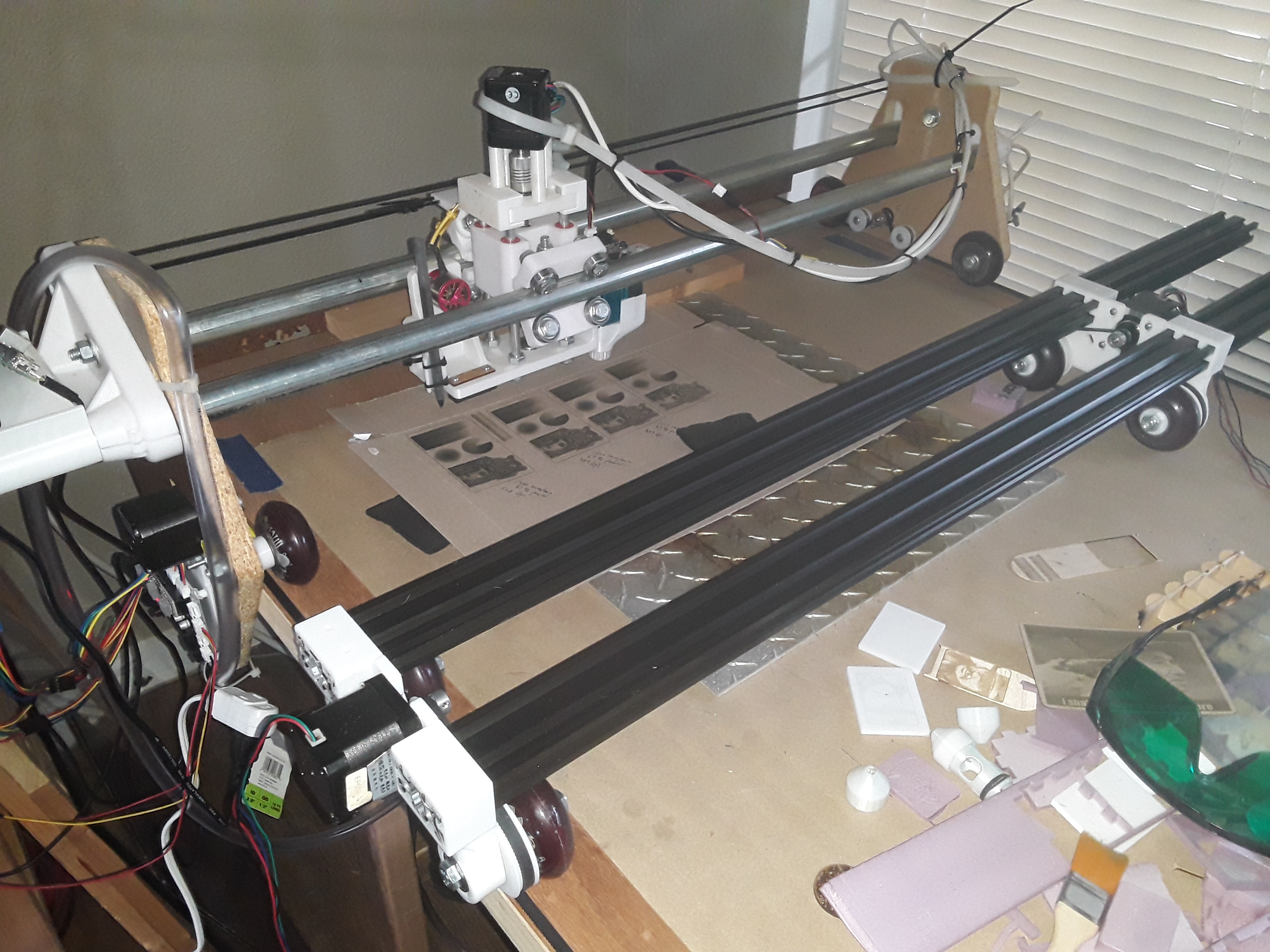
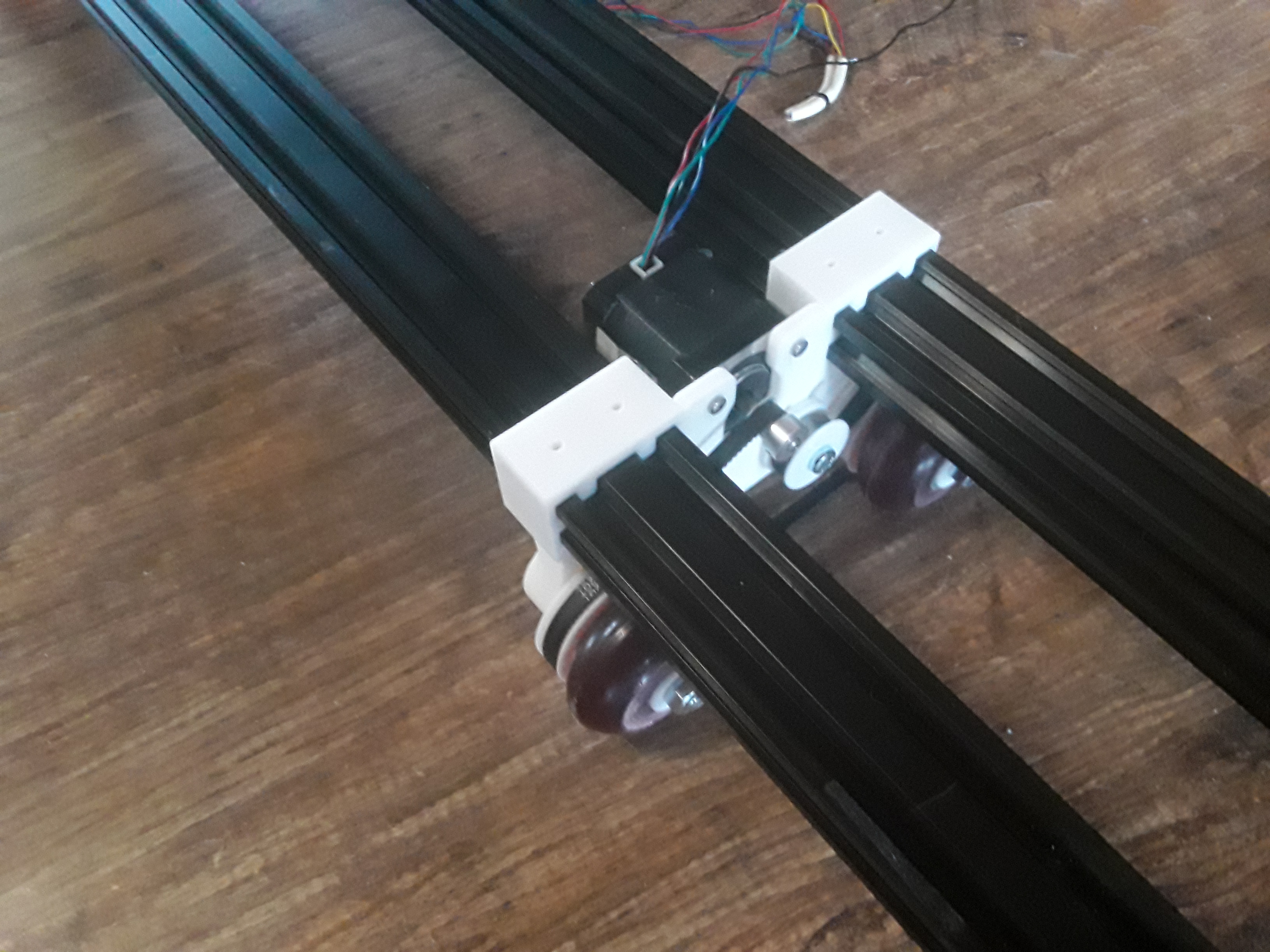
In this design the skate wheels, instead of free-wheeling, are driven. A printed 78(?) tooth wheel hub fits snugly where the inner bearing ordinarily goes and a simple filler hub replaces the outer bearing. A 444 mm closed-loop belt, an idler bearing, and a stepper motor and drive gear round out the drive mechanics mounted on the endplate…

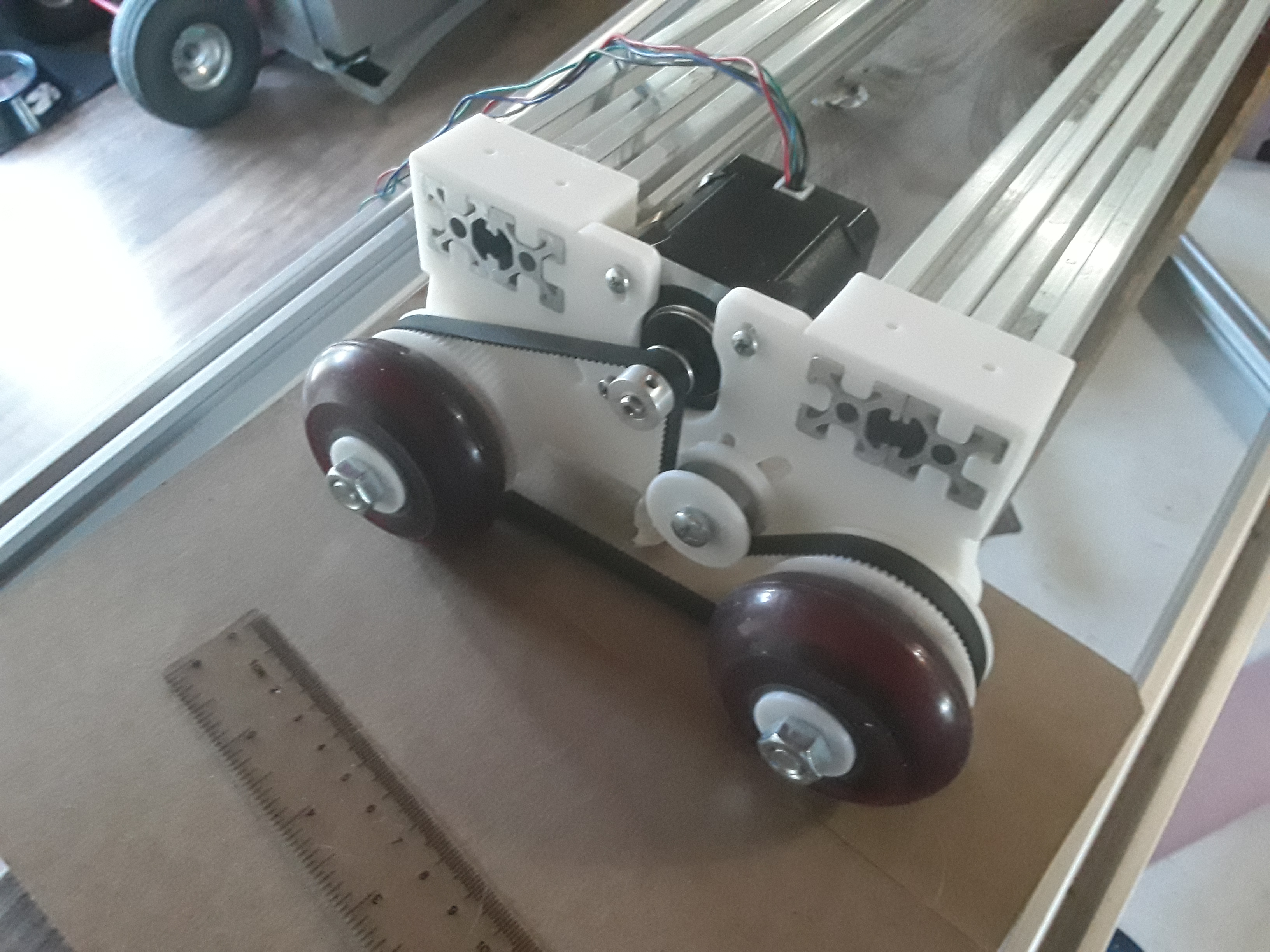
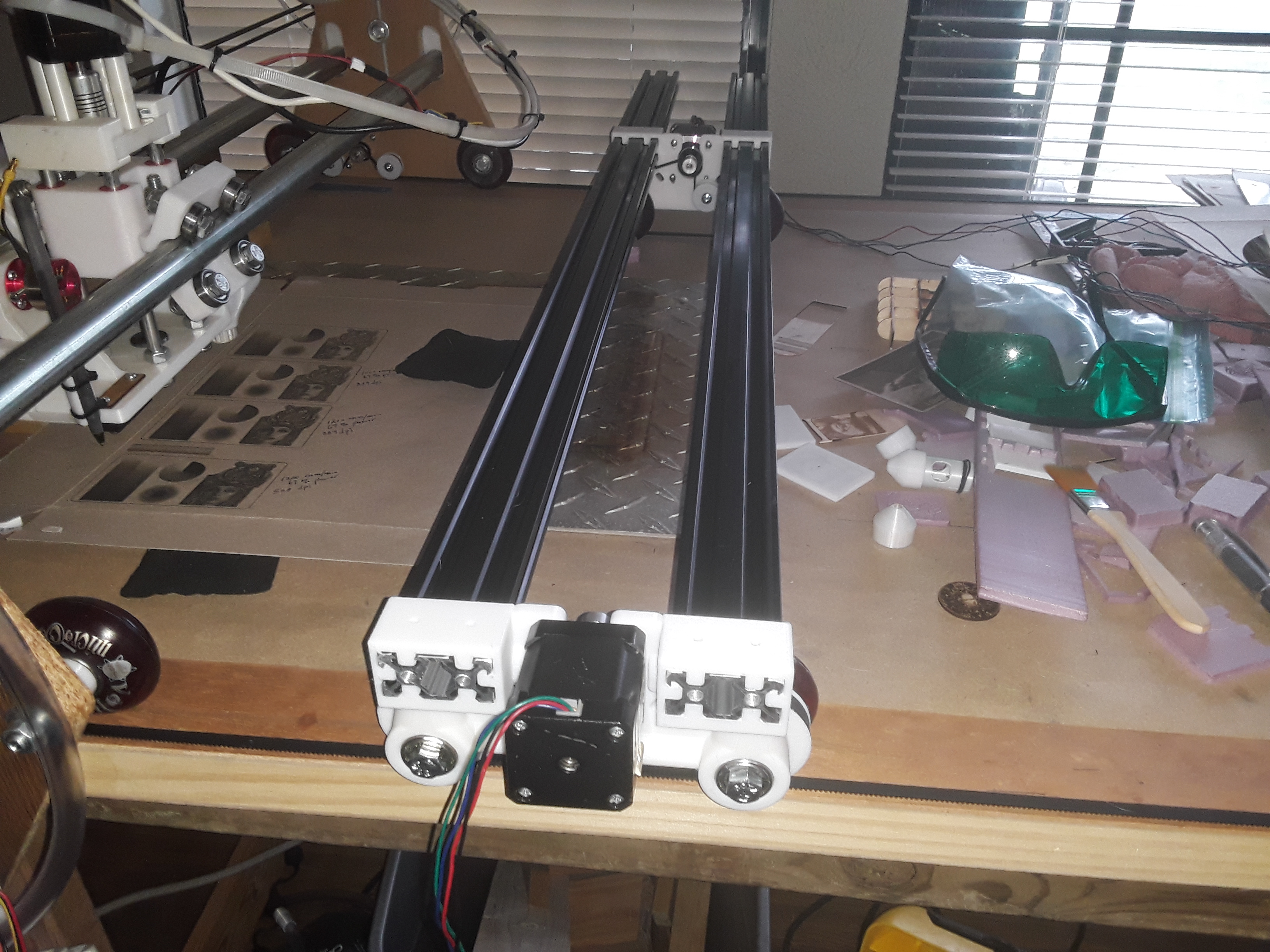
I also modified the extrusion to endplate connection to allow adjustable spacing/span between the drive wheel assemblies. It also allows for reversible endplate installation… wheels inside or wheels outside.

Though the rails are shown flush in this photo, I suspect any excess rail could hang over at this end to allow a small shelf to be affixed for the electronics and display… similar to the existing gantry.

Next up, I’ll try to get the motors wired up and move this axis… which will be the X-axis. I then hope to be able to use Dave’s motor and idler mounts and moving carriage/plate for the Y axis. Finally I’ll take a look at his Z-axis… I can’t remember off-hand whether he wound up using a stepper or servo. Once all axes are moving properly, plotter functionality will be the first order of business… and the obligatory crown. Then… probably laser.

Always fun, a new machine build. Later.

– David

5 Likes

I look forward to watching your build. I added a link to your build log on the thingiverse design page.

1 Like

Wow! I guess I’d better commit to this thing then, right? :astonished:

Funny, somewhere along the way I’d forgotten(?) you had put your design up on Thingiverse. I had downloaded your STL’s from the Openbuilds site… are these the same as out on Thingiverse?

I feel you are giving me more credit than I deserve… after all, I was just following your lead on this thing. I see my efforts only as a “remix” and “use case” departure… more lumped in with the “lots of possibilities” aspect of you design. Your efforts and original Rolling Plotter design and use cases are the only true reason for its existence… mine is just a “spin” on your work.

Thank you, Dave.

– David

The newest version of the design is on thingiverse. Maybe I should update or delete the files on openbuilds to avoid confusion. I thought it would be good for others to see possible alternatives to this design. I like your idea of having the V-slot go thru the end plates. Question for you on the bearing spacers. Did you have to add any spacer to the bearings on the end plate? Not sure there is much room to put a spacer there, but maybe a washer.

Well, thank you… that does make sense then. I really hadn’t thought that far ahead… just assumed I’d put my modded parts out there someday, as a “remix”. For grins, I’ve tried my hand at creating a STEP file of my endplate… just unzip it. It should import into Fusion? Though I elongated one of the idler slots (did that one in Tinkercad, before I started playing with STEP), it should still allow you to use your same idler setup.

rp_end_plate-dkj.zip (2.4 MB)

I did create and install a spacer for the bearings on my endplate… it’s the same width (as close as I could measue) as the ridge between the bearings when fully seated.

There are no wheel bearings in my design and the axle rotates with the wheel…

Hope that helps.

– David

Some progress…

Wired up the plotter/gantry and got things moving in the proper direction. Did a quick, rough, steps/mm calibration and the to & fro motion here ranges over +/-150 millimeters, total 300 millimeters.

Picked one of my little Nano-based Grbl controllers from my stash and verified its running Grbl v1.1h. I have the motors wired in series, ala MPCNC… running on one DRV8825.

Slid the trucks/tractors on to shorter lengths of extrusion for test purposes…

There is a slight drift away from the camera in the video. I’m believing wheel friction on one side may be greater than the other… I just tightened until there was no wheel play that I could tell. I’m sure that a side-board or guide of some kind will be necessary to do accurate work.

It’s a start…

– David

1 Like

Does the version of GRBL make a difference or just current 1.1 version?

No, it doesn’t… these are simple motion tests.

I had flashed several Nano’s and just pulled a couple out of my stash… quickly plugged them into my Chromebook and used the built-in Gcode Sender app to verify. With all the Lightburn and laser work I’ve been doing recently, v1.1h and “laser mode” are my preference… and I suspect some day I’ll put a laser on this thing anyway… :wink:

1 Like

Okay… got new endplates printed, added a new Y-axis, and ran a few motion tests. I had the accelerations set pretty high initially and it almost did “wheelies” on the floor! I toned them down for this simple test…

Simple Nano-based Grbl 3-axis controller and Pi 3B+ running Jeff’s V1P1 image and CNC.js… runs from the browser on my Chromebook.

I was able to adapt the ERC TimSav’s “skinny” axis to this machine’s Y-axis. Printed a smaller motor mount plate…

and a fancy tensioner somebody out on the FB group did early on…

The belt actually runs inside the extrusion channel and there don’t appear to be any clearance issues where it passes through the endplates.

I’m sorry that the black extrusions don’t really photograph detail very well. I now need to start looking at a Z-axis. I built one I really liked once before but it’s on my daughter’s laser engraver… need to hunt it down again. And, of couse, need to mount all the electronics stuff on board.

Finally, I need to put it up on the FoamRipper’s worksurface… turns it from rolling plotter to gantry?

Later. – David

1 Like

Looks good. A video of it doing the wheelies would be fun to watch. Glad you got that belt system to work for you. What size timing pulley did you use on the motor?

1 Like

All the pulleys on this machine are probably 16- or 20-tooth IIRC. Most of the time I don’t really care too much as I actually command and measure axis movement and adjust the steps/mm to get them to match. Edward Chew’s TimSav documentation calls out a 20-tooth pulley for the hardware I stole from TimSavX2 (now being dismantled) so that one is probably 20-tooth… and steps/mm of 80 seems to confirm. The other axis, with 78-tooth printed pulleys, has a steps/mm of 83.88 for proper movement… so not sure.

The “wheelies” thing appeared as “bounce” as the axis changes direction. I had to add the weight of my little bench vise to hold it down with higher acceleration values. I ultimately just slowed it down until the tractors quit bouncing with a direction change.

1 Like

They are probably not 16T as the belt seemed to catch on the sides of V-Slot when I used them. I did not have any 20T at the time. My 1st new endplate print pulled up on the corners, so I leveled the bed better and trying it again today. I don’t have the heated bed for that machine hooked, but that would probably fix this problem. I added some more holes to the plate to have more perimeters & using less infill thus giving a shorter print time. Will see if it is strong enough. Should be less than 2.5 hour print where yesterdays print was close to 4 hours.

Alright…

TimSavX2 is no more. SIL finished his large foam project for his church’s children’s room… and I have no real need for such a machine…

Still have a TimSav to play with…

New horizontal surface to start piling stuff up on…

Go to thinking… what’s better than FoamRipper? TWO FoamRippers! Or, at least, one FoamRipper… and a Mini?

Still have the cutoff door piece from FR… could make a MiniFR. Lots of stuff I do really doesn’t require the full area of FR and this might be a really handy size. At the very least, it’ll be easier to get around it to work on during further development.

Gotta spend the hours of my day anyway… why not piddling with this stuff?

– David

3 Likes

This is perhaps a bit much to attempt, since it looks like it requires two 6 axis arms.

Scaling back the number of dimensions, I would think with a pair of 2-axis controls that are controlled independently instead of synchronized to each other you should be able to cut out a 2D shape and also control the slope of the edge. For an object sliced into layers you might get a decent approximation.

If your object is convex then dual 3-axis controls should be able to cut out the shape with a straight wire between them. I’m not sure what you would make with it…

1 Like

That is way cool, Jamie! But I really have little need for a hot-wire machine now that SIL has completed the foam project he did for his church. So I’ve actually dismantled the TimSavX2 hot-wire machine I built… leaving me with one TimSav 2-axis CNC machine (to play with on down the road) and a bunch of parts I can use to finish out this rolling plotter/gantry project.

But that is cool. I’ve never messed with robot arms… too many degrees of freedom for my tired, old, brain to deal with. :wink: :face_with_head_bandage: