I ordered the full kit from V1E with the preprinted parts and the Jackpot board - they showed up on Thursday and I spent the weekend building it out so thought I’d do a quick post. Everything went pretty smoothly.
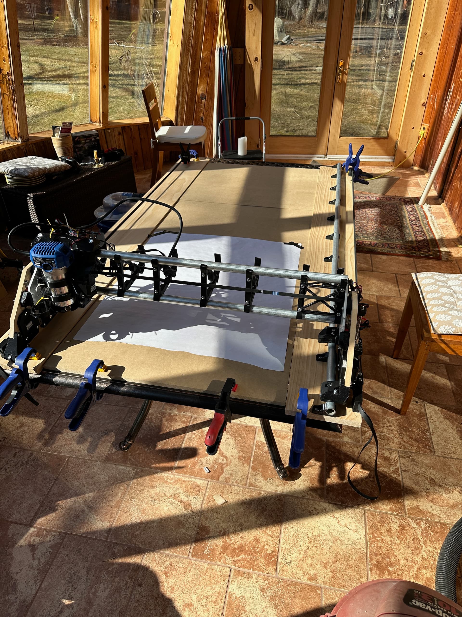
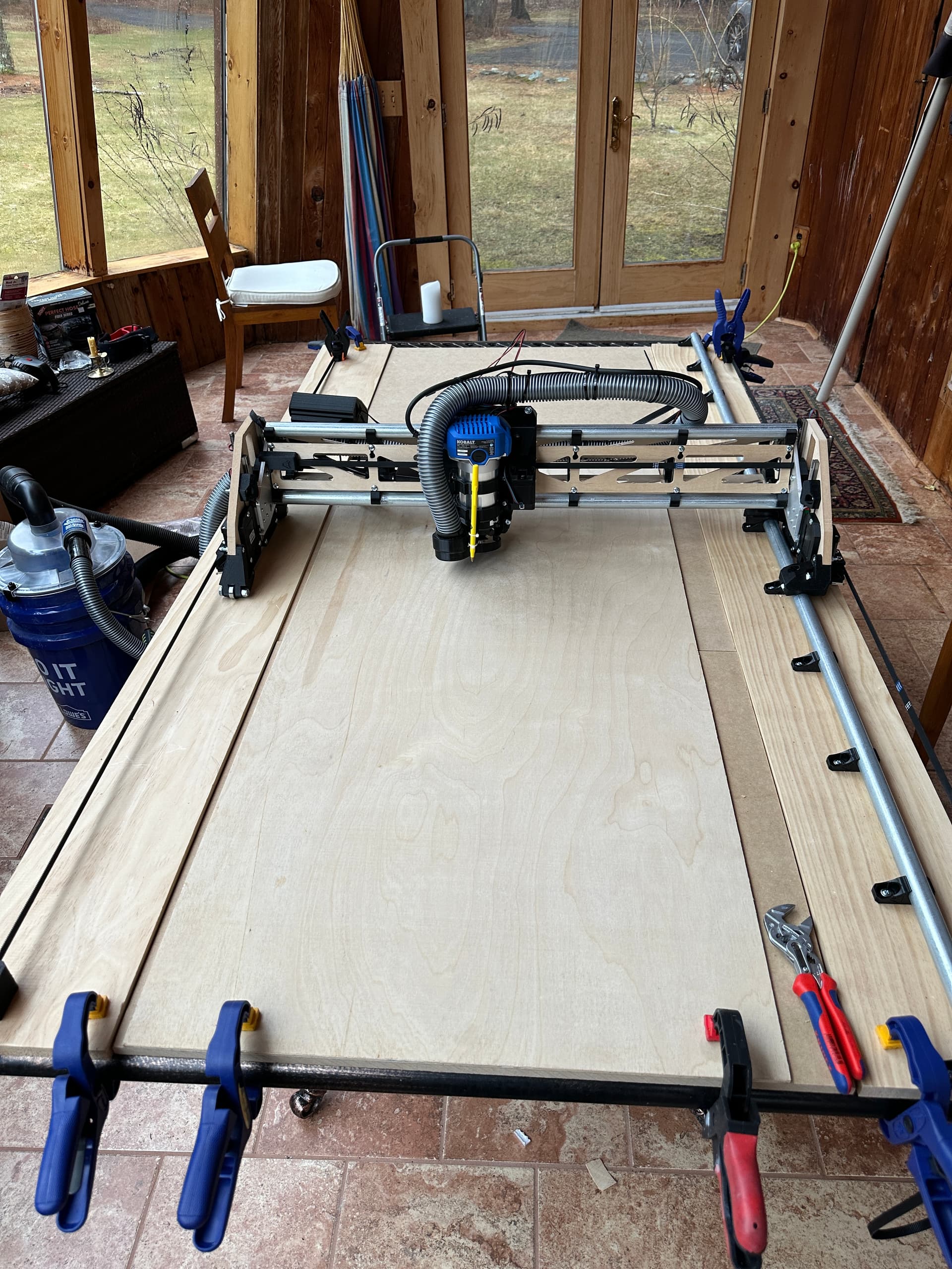
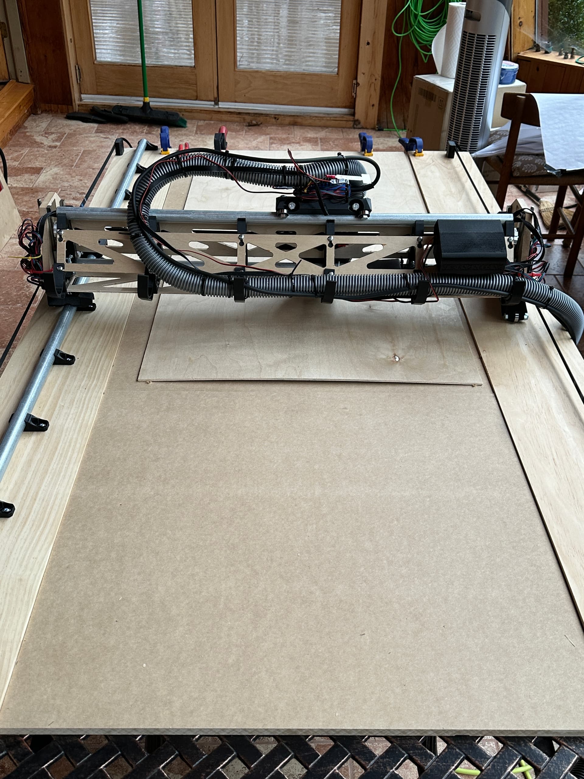
My biggest fear after reading the forums was the table - I have a long table in my basement and was planning to just bolt everything to it, but wound up making a more flexible breakdown install that so far seems to work just fine. My cutting area is about 26"x65" but the layout would work the same for full sheet. I pretty much just put the y rail and belt on 6" wide boards, and then cut some mdf slats to fit between them for a scratch surface.
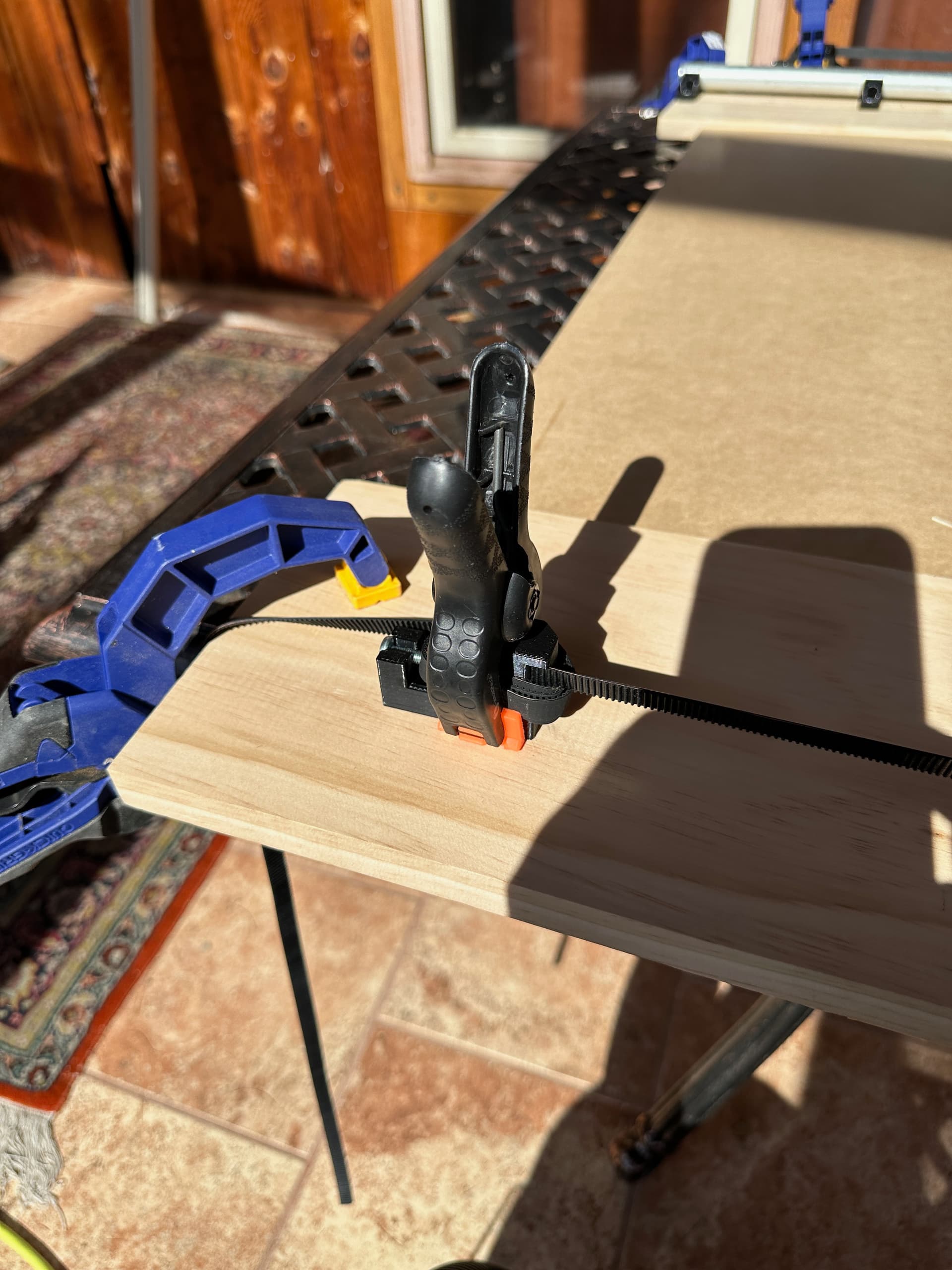
It was a nice day so instead of putting it in my basement I wound up putting it on a table on my porch. Setup takes no time at all. The belt stays threaded into the lowrider when removed - I just unclip the front end (which is already in two pieces) and for the back end I just clamped the belt to the block instead of using the screw tensioner. Taking it apart takes two minutes, putting it together is mostly about lining up the boards so the Y-Axis switches click at the same time.
I ran the wiring from the far side through the upper tube and that seemed to work out well.
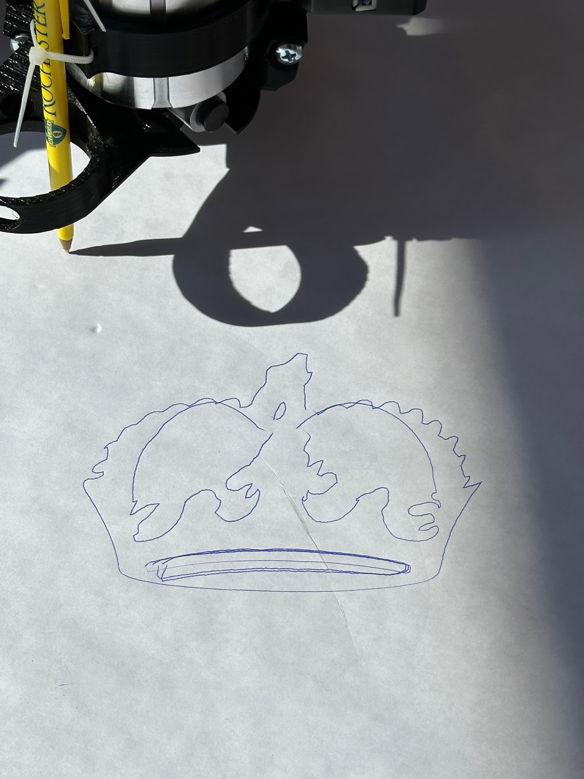
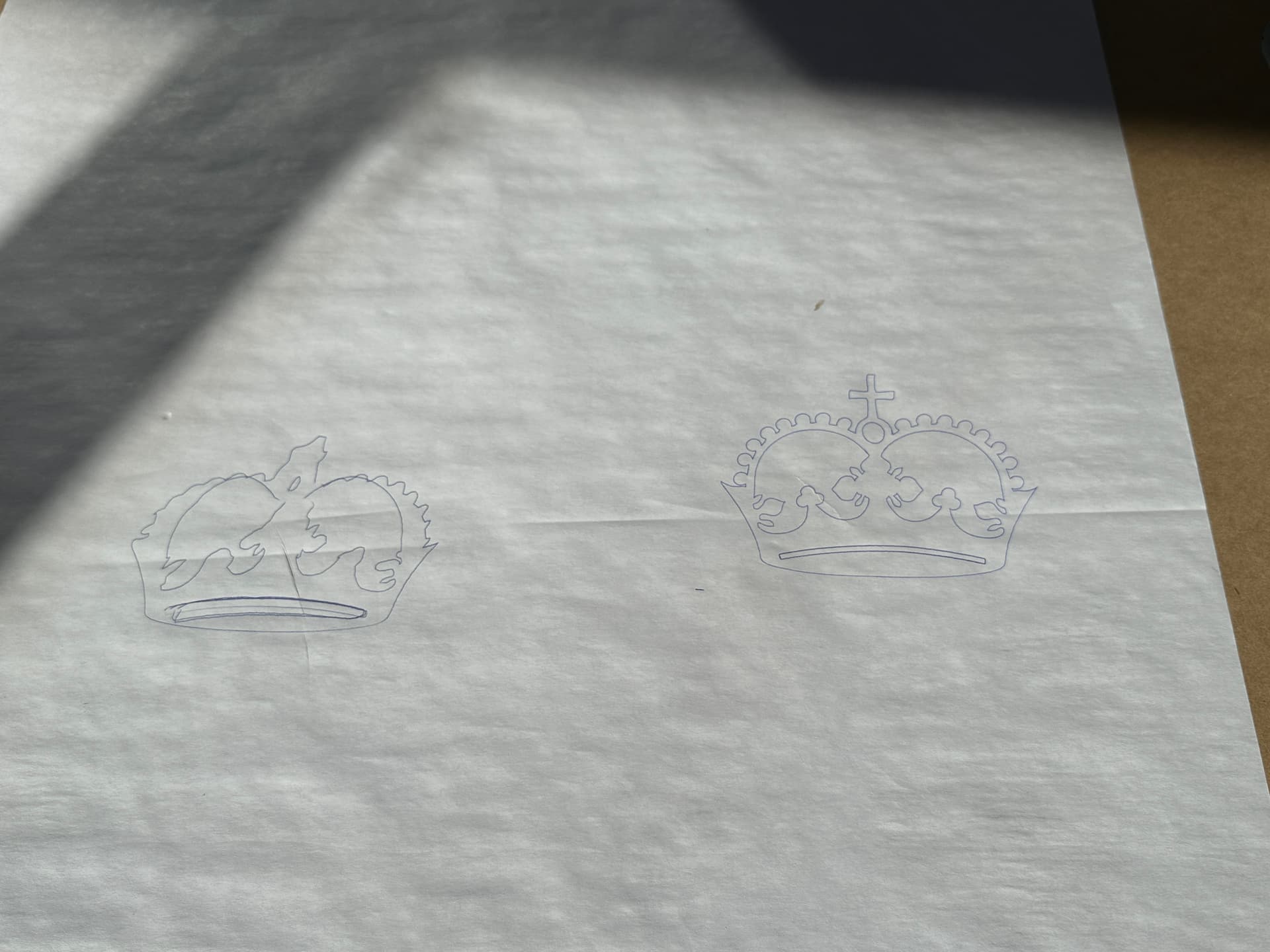
I ran out of time before I got to cutting the struts, but I made it to the crown. The pen was very loosely attached and tilted on every motion so my crown looks like it was drawn by a toddler, but the lowrider seems precise. I should probably redo it just to be sure, but I ran out of time so enjoy this Impressionist crown.
@vicious1 Thanks again for everything!
A few things that would have been helpful while they’re fresh in my mind:
A clear diagram showing orientation and X+/Y+/Z+
Add the Tiny Touch Plate as an option on the Hardware Kit page
Update various pages (the lowrider page, the estlcam-basics page, the software page, and wherever else) to include the Jackpot board. For instance I’m actually not sure if I’m supposed to use Repetier-host with the Jackpot or not - I couldn’t get it to connect over TCP/IP so just uploaded the gcode directly to the Jackpot SD card and had FluidNC run the code, which seemed to work fine.
A couple of extra red spade terminal crimp connectors in the kit. Nothing like the feeling of screwing up the crimp and getting stuck over a .10c part. Wound up cutting off the sleeve, forcing apart the crimp and soldering the wire. I miss Radio Shack.
Thank you for the feedback! Sorry it is not more complete. I am taking some notes to try and make some changes for the next builder.
For the crimps, what is a good spare number? I include one per kit, and have not had feedback until now. I can have more added but I do not want to waste too much.
Hi Ryan! I didn’t see the spare but in any case the truth was that I busted two of them. Entirely my fault - I have a good stripper/crimper but I just wasn’t doing it right. I had checked my local Lowe’s but they only had 1/4" spades. Didn’t think about the automotive stores but that’s a great tip. If it’s just me then it’s probably not worth worrying about, and it was easy enough to work around once I decided to just go ahead and solder it.
I’m really happy with how well everything went on the build front. Looking forward to getting the struts cut and finishing it off.
I had the same thought on the crimps. They were a real beast to try and get them onto the spades of the limit switches. I just ended up soldering them on instead, with the thought, If I need to replace in the future, I’ll just snip and re-solder.
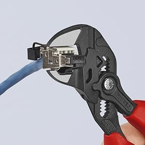
Yeah, sliding on the spade connectors was a pain. After some struggle I found that using a parallel closing pliers on the edge of the connector worked really well to push them into place without bending anything. The Knipex Pliers Wrench looks like a normal pliers but is actually a magic tool - I use it for everything. The jaws always close square to each other, and there’s no slippage - it doesn’t round off bolts like an adjustable wrench, it doesn’t scratch because it doesn’t slide - my goto for almost anything that needs gripping nowadays.
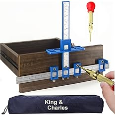
On the tool front another item that came in really handy was this cabinet jig - it was perfect for getting the holes exactly lined up for the Y rail. It’s been surprisingly useful for way more things than it advertises. $10 for the plastic one.
Well, I think I’m complete on the build. A few more pics to follow up my original post above:
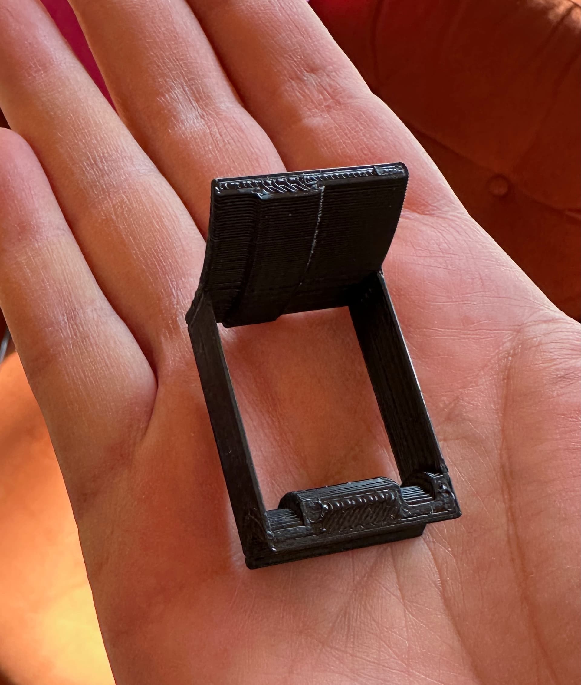
My wobbly crown was indeed due to the pen being very loosely attached - once I secured the pen holder it came out much better (and I probably should have made the pen itself even tighter):
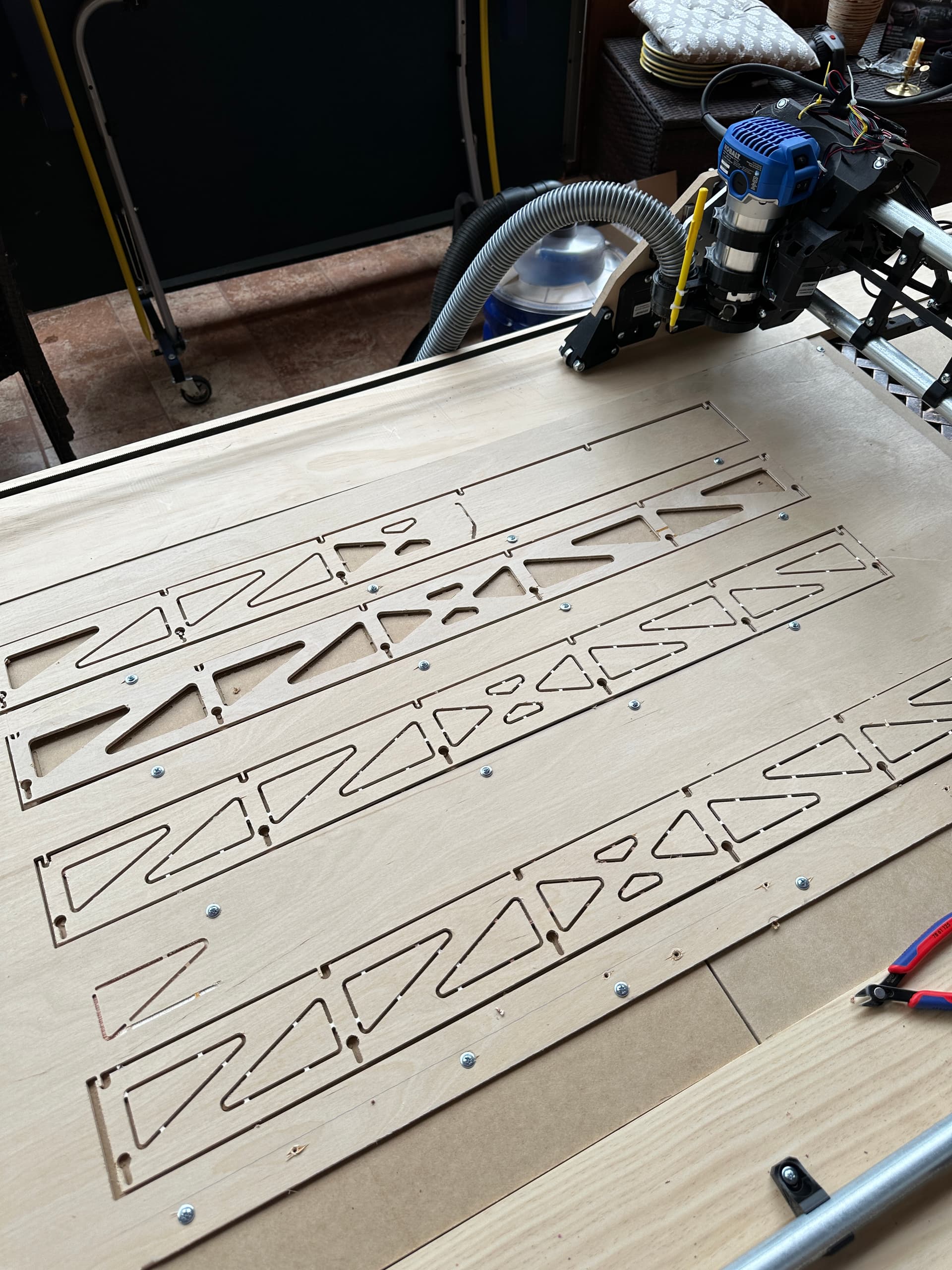
Cutting the struts went mostly ok, once I figured out ESTLCAM and where to put tabs, etc. I lost the first one halfway through - my 1/4" plywood sheet wasn’t screwed down tightly enough (and closely enough to the cut) and pulled up a bit, enough that it wound up cutting through the tabs and the piece came loose. Put a bunch of screws on either side of the next strut cutline and after that it worked really well. I put them back into place for this photo. (The fourth one there started off a bit haywire with that scratch so I aborted right away.)
I’d say about 3 full days of effort, starting with the hardware kit and pre-printed parts from V1E. Most of that time was also spent binge watching Community while assembling, so YMMV.