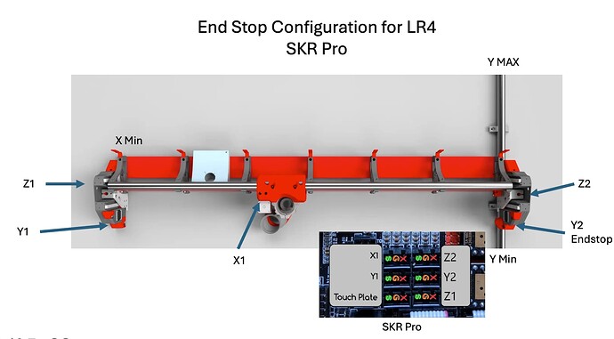
The LR4 was built with more End Stop configurations than needed for the typical build. I put this graphic together to confirm I have it right and if correct, hopefully help others. I was not able to find a clear instructions online. I apologize if I just missed them.
I’m not building an LR4 at the moment, so I can’t confirm 100%, but based on the LR3 (which the LR4 was based on) , I think that you have the Y1 and Y2 on the opposite side of where they’re supposed to be (should be on the router side of the gantry, not the back side).
Perhaps another user can confirm this…
As a bit of background, during the Beta process, some users requested the ability to home to either XMin (normal) or XMax (reversed) and to either YMin (normal) or YMax (reversed).
This was to allow those who refuse to follow the Yellow Brick Road to Oz (and prefer the scary woods leading to the Wicked Witch’s castle) to change from Portrait orientation to Landscape orientation.
The extra end stop locations that you see are unused in a Yellow Brick Road build. It seems like that information may not be clearly stated in the instructions.
If you want to update your graphic to label the unused locations (and to show Y1 and Y2 on the router side), that would certainly be helpful to other users, and may be something that @vicious1 would want to include in the instructions???
I edited your post to remove that incorrect image.
Perhaps the wiring instructions could be expanded upon? I’m also really lost and have been re-reading the instructions and these forums looking for some more information. I’m about to wire up my LR4 today.
The instructions said to label the endstops as Y0, Y1, X0, X1 etc but then in the control board it has slots at the bottom for Y1, Y2… I would be very grateful if someone could ELI5 for me, how to wire it up and which wires do what.
Besides this, which I will be working on, what else is not clear.
To me this does not have anything to do with where the end stops are. I want to fix both misunderstandings. What made you put the Y endstop in the back and not where they are pictured?
To explain this further, Marlin firmware and every machine prior to the Jackpot board used y1/y2. FluidNC and the jackpot use Y0/Y1. I will either add another picture or delete that picture and just use a chart. This issue seems to hang up a few people. I did not expect it to be an issue, lesson learned.
Hey Ryan, Thanks for the quick reply and the correction. I have been pulled away a lot from this build and have lost some of my continuity. In the picture you posted, I saw the end stop, installed it… When I added the second bearing assembly on the other end, I saw the place for an end stop and thought it needed it. When I went back to the direction, I think I got a bit lost in where Y and X max and min. I am a picture guy and that’s why I made the illustration. Is this one now correct? Including MIN and MX?
This image is exactly what I need to help my brain understand it.
People just learn in different ways. Thanks gents!
yes…kinda
That is correct for an skr marlin. An skr/marlin users, use Y1 / Y2. jackpot uses Y0 / Y1
I updated the jackpot page to help some, not sure what I am going to do about the skr and all the other marlin pages.
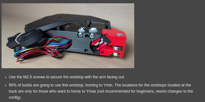
be very careful with that rotated and cropped endstop image, if you plug those wires in wrong you will kill your board.
LR4 is my first time around any CNC. Mine is built just getting ready to build a table. I had a couple of times where I was confused on end stop placement however figured it out on the forum. Maybe add a pic in the instructions of a complete LR4 with arrows pointing to the standard location would be helpful. Just my thoughts. This machine impressed the heck out of me and mine is not even running yet. Thanx Ryan
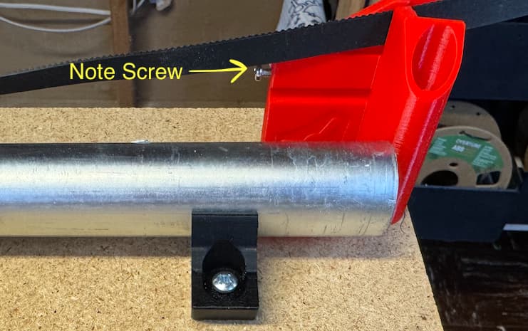
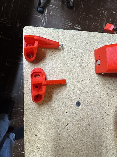
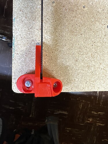
The EndStop hits the Y belt tensioner where you see the screw in the one pic. Follow Ryan’s instructions closely you need to have the distance fairly close so the end stop hits the screw. Great engineering, you just can’t partially skip through the instructions like I have been doing. ![]()
I repeat: the screw should be all the way in. ![]()
Thank you!
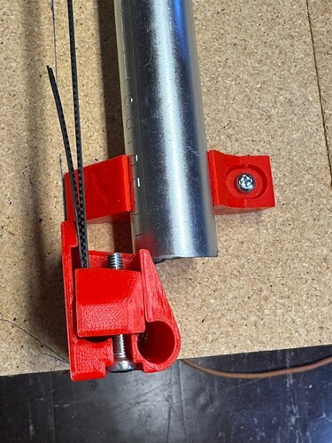
To start with, it does typically need a couple turns out to work. Less than what is shown in the picture though.
I’m using a jackpot board. It’s my understanding that wire direction shouldn’t matter on that board for both end stops and stepper motors other than I might have to flip a stepper motor around. Am I wrong? I just want to clarify before powering my board for the first time.
Russel we should have you start your own thread, You have a jackpot and this thread is about the SKR labels.
The jackpot end stop polarity does not matter, and since it is our own board we have the power rail removed so you can not short the input pins.
So one more mistake I made, somehow I had the angle of the endstop off and it was so minor that I could not adjust it enough. I made a modification to Y_belt_minf and added an additional screw that allows for some slight angle adjustment.
That’s a pretty good idea. ![]()
