LowRider 3 - Plasma Build "On a Budget" - Clarksburg, WV

LowRider 3 CNC DIY Plasma Table PART 10 - MESA torch height control!

MESA THCAD-2 SCALE AND OFFSET:

Kudos again to Kyle, @kd2018 for his custom calculator as linked in his post here:

…which, as of today is still available here:
https://jscalc.io/calc/NTr5QDX6WgMThBVb

Since the THCAD-2 can (essentially) emulate a THCAD-10, I used the calculator with “10” selected.

Here are the values, and a screen shot, for how I calculated the scale and offset for my THCAD-2:

Scale:		0.01002130
Offset:		3,093.7500

Based on:

Output frequency at max voltage from the calibration sticker (kHz):		897.3

Output frequency at 0V from the calibration sticker (kHz):				 99.0

Frequency divider jumper setting:
	F/1
	F/32	<- selected
	F/64
	F/128

THCAD Model:
	-10		<- selected
	-300

Plasma Machine Voltage Divider Ratio:							25 		
->	 "25" : For my 1:1 plasma machine with an HV resister (2.4M) inserted 
			externally on the negative lead, all based on guidance from 
			MESA's Peter C. Wallace ( @PCW ) on the LinuxCNC forum.

Isn’t that built into qtplasmac now? I don’t remember needing to do that step. I need to have a second look for sure, since I am not convinced my thc is working 100%. Looks like another week of storms here, so not testing for a while.

-edit-
I just checked, I was wrong it does not appear to be built in,

1 Like

I am definitely on qtplasmac now, and I was doing the calculation simply because I saw Kyle had and so I thought it would be needed somewhere! LOL

Sorry was editing when you replied. Those numbers you calculated are needed in QT, but I swear I just input my sticker values somewhere, maybe in the initial config. I am going to double check.

While I was just poking around I did see a see stepper config test, I want to see how fast I can push the machine. Plasma definitely benefits from fast moves and accels.

1 Like

@vicious1 and @kd2018

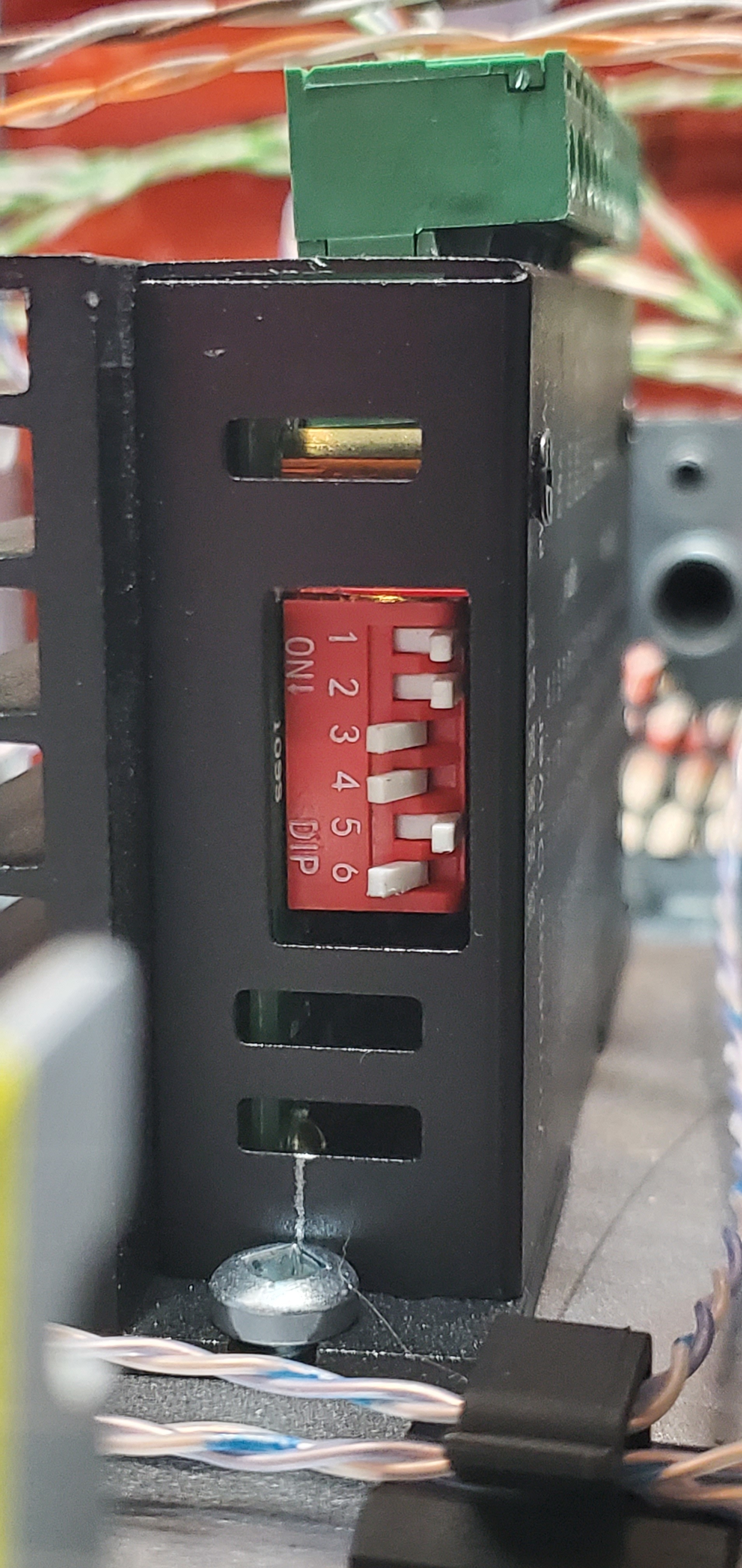
How do you have your dip switches set on the TB6600 stepper drivers?

Below is how @Trevor has his dip switches as per this thread:

My power supply is Mean Well LRS-200-24 — 200W 24V

Would I be presumed OK if I did mine the same as Trevor?

EDIT: I just noticed his power is 12v and mine is 24v. So I am guessing mine will be different.

Im looking at the chart on top of the TB6600 for the switches, and I’m struggling to understand it all.

No those set the current so voltage doesn’t matter. I can check when I go out to the shop in a couple hours, but it looks like I only have the top two off.

Thanks!

First three are microstepping, I used 16.
Next three are current, I used 0.5 with a peak of 0.7 - the reason I dislike these drivers. I would prefer 0.7 peak of 1a. If I find anything lacking in my speed tests I will swap these out for drv8825’s

1 Like

Okay maybe I did mess this up.


This doesn’t look right…

Nevermind it does seem to be right, QtPlasmaC, I can use that calculator to double check the values inserted into the qt screen though. I really need to test this on some longer cuts.

Here’s the back of my THCAD2, and a screen shot of what I inputted during PNCconf:

Nevermind it does seem to be right, QtPlasmaC, I can use that calculator to double check the values inserted into the qt screen though. I really need to test this on some longer cuts.

In that video it shows on and active, the voltage is all over the place though. I think I need to increase the Z axis accel and speed.
Sorry for doing this in your thread, but I think it might be relevant to your build. As mine sits I do not think it will do the corrugated test, but after some tweaks I hope it will. ramp or wavy

1 Like

I am very grateful for all your posts on my thread. It is hugely helpful to me!

That kicks out the same numbers you calculated automatically into the qt settings screen?

I have not yet had a chance to check, but I will.

Love the video! That’s so cool that you have a working setup!

I’m still trying to get my steppers and end stops wired up, correct and working. I have yet to see a sign of life in my build!

1 Like

No, as far as I can tell, the values in QTPlasmaC ( Parameters > Configuration > Arc > ) Voltage Scale and Voltage Offset do not match values I got from Kyle’s calculator.

I’m not sure which to go with. If I want to try to go with Kyle’s calculator numbers I guess I would edit that in the INI file. ??

Below is a screen shot from QTPlasmaC.

Note: at the time when I ran the LinuxCNC PNCconf wizard, it was not yet updated for THCAD2, so I had to go with model = 10, but since then a guy on the LinuxCNC forum informed me that he updated it to have a dropdown choice for THCAD2.

Also, at the time when I ran the LinuxCNC PNCconf wizard, it was not yet able to accept any 0V Frequency (kHz) lower than 100, and my THCAD2 says 99 on the back. So, I entered 100.

The difference between 99 and 100 affects the results of Kyle’s calculator slightly.

Kyle’s calculator, for my setup, with 0V Frequency (kHz) set to 99:

Scale: 0.01002130
Offset: 3,093.7500

Kyle’s calculator, for my setup, with 0V Frequency (kHz) set to 100:

Scale: 0.01003386
Offset: 3,125.0000

Still neither of those sets of values matches what QTPlasmaC is showing.

I barely understand how this works but I would venture to guess that is close enough. It is in the end a pid so it will keep moving until it finds the target. As long as they are close it will get there either way.

Most import are the Z speeds and accels, and what I think did wrong, is went too conservative with the Z values. The faster it moves, the faster it gets to the target.

1 Like

Agreed!

FWIW, I don’t know if this is still the case but in the early days Phill strongly resisted putting a calculator in plasmac. He advocated that people should measure actual voltage with a multimeter to calibrate their raw voltage reading rather than rely on the numbers on the sticker. And the should be running test cuts on the material they intend to cut and find what voltage set point works best for them rather than relying on plasma machine mfr cut charts.

1 Like