LowRider 3 - minor mod - bladeless homing - 'cause blades keep coming off - thoughts and observations

So, like many of you, I’ve had the little thin metal blades come off my homing / end stop switches.

As many of you already know, but in case some don’t, the little blades serve a purpose, which may be more important or less crucial depending on the circumstances.

The purpose of the little blades is to trigger the end stop switch before the machine’s moving parts have run out of room to move, because of lag or delay in stopping after the switch is triggered. The concept is that there may be a delayed reaction, and so a little bit of leeway is helpful.

This need of extra space becomes more crucial when the moving parts are moving quickly, and when they are very heavy, and if both those moving parts and what they are colliding with are firm with little to no give.

So, if the homing speed is low, and/or if the mass is low, there is less chance of trouble by going bladeless.

I felt my LowRider 3 qualified on both these counts.

After losing one of my blades yet again, I decided to test bladeless homing on the end stop switches. For this current time, I removed blades only on the one X axis switch (which for me is Y because my X and Y are swapped), and both the Z axis switches. The Z axis homing speed is particularly slow and careful, and removing the blades seems to work just fine.

I did have to make one change to get this to work on the X axis (Y for me):

  • I had to glue a thin strip of printed plastic onto the end stop (that the switch hits), to get the switch triggered a bit earlier than would happen without it. This was needed because the lack of a blade meant the distance offset offered by the blade is gone, and I needed to reach the switch as early somehow, lest the hardware all hit the physical limit at the side. (Remember, since my X and Y are swapped, this was to prevent a collision at what for most of you would be the “X-max” side.)

This worked great.

Also, similarly I did have to make two changes to get this to work on the Z axis:

  1. I unscrewed the printed holders for the Z homing switches, and flipped the switches around, to get their little switch nub closer to the protrusions on the XZ plates, and then reattached the holders.

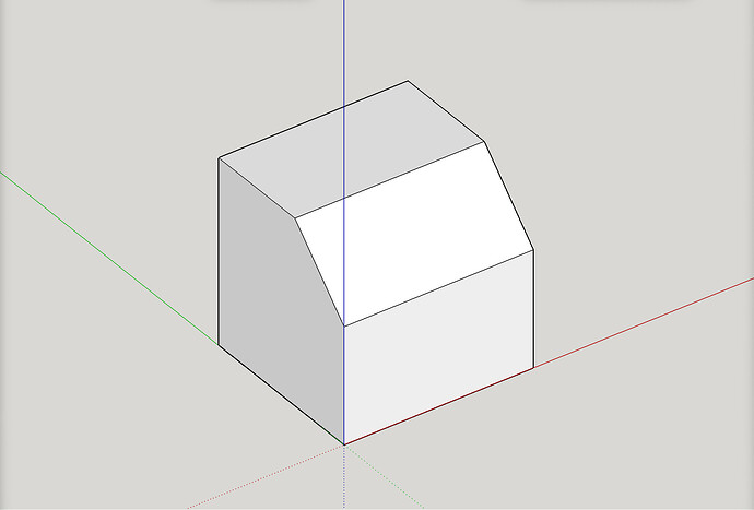
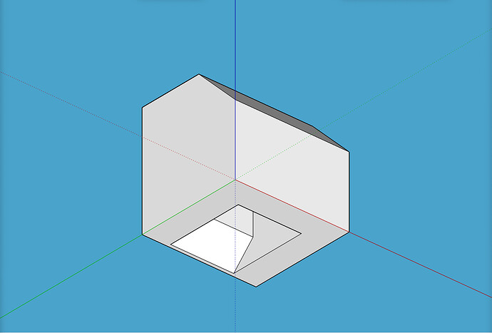
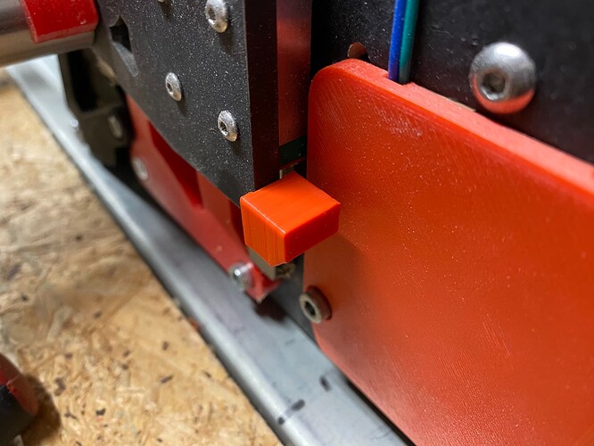
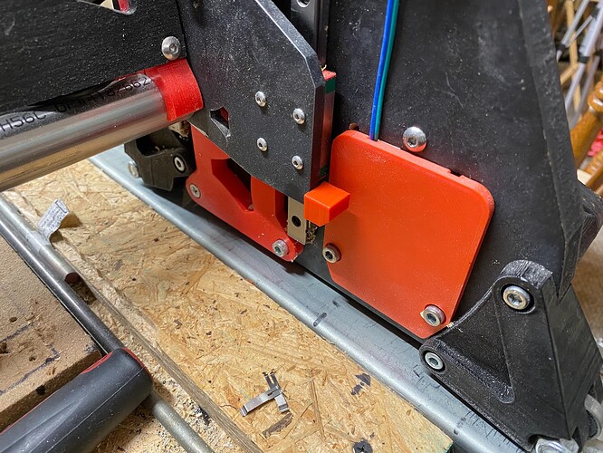
  2. I designed and printed two little “boot tips” to slide onto the protrusions on the XZ plates. This was needed because the realignment in step 1 was not quite enough, and the lack of blades meant the distance offset offered by the blade’s is gone, and I needed to reach the switch as early somehow, lest the hardware all hit the physical limit at the lead screws, i.e. the printed trucks on the lead screws banging into the top of the opening in the YZ plates.

This worked a treat.

Finally, while I have not yet removed them from the Y axis switches (again, X for my machine) I’m already halfway ready to do so if the need should arise, because my mod to hide the “near side” long belt inside the unistrut/superstrut meant that my end stop is already positioned to trigger the nub on the switch even if there were no blade. My non-mod’d other (far side) long belt would need attention to get such a connection.

For now I’m working with homing this way and it seems fine.

Download link for the little boot tips:
https://www.printables.com/model/421700-lowrider-3-cnc-mod-boot-tips-on-protrusions-on-xz-

PS: I’m using steel XZ plates bought from Ryan in the V1 Engineering store. These would also work with aluminum plates too. They may work with printed plates as well.

Below are pics of the little “boot tip” on one of the XZ plates:

Design

Printed part:
2 Likes

I’d be interested to see if this has an impact on precision in scenarios that rely on the endstops for repeatable accuracy. I was under the assumption that the throw of the metal arm increased the accuracy of when the switch was triggered closer to the fulcrum point… but that is an assumption based on nothing really.

With that said, Doug, you are a big asset to this community. I don’t know how you have the bandwidth to be perpetually tinkering with this stuff, but I’m here for it.

4 Likes

Thanks! I’ve seen various posts where people were referring to having tested their homing process for accuracy. So I know it’s doable, but I’ve just never done it, and I’m not even sure how it’s done. I know I can look that up, but if anybody can just tell me, in a nutshell concept in a sentence or two, I’m happy to try. However, I am loathe to put the blades back on, so I could not do a before and after comparison, but maybe someone who still has the blades on could test to see what kind of “before” accuracy they’re getting.

I guess just home and draw squares?

Throw just gives a bit more “give” before things hit hard stops. The probe for my 3d printer is an omron micro switch with no arm. Same as my x and y endstops, no arms.

1 Like

If you have a micrometer, the best is probably to home, go to some location like X=10 and set it up at zero. Then home again and jog back to 10 to see how far off it is. Repeat 10x.

There is an electronic way to do it, but I have only done it with my bltouch. I am trying to remember how I did it.

G38.2 would be good. But I don’t think it works for anything but the probe. You should probe towards the target, have the endstop wired in the zmin port. After it stops, M114 should tell you where it thinks it is. Rinse. Repeat.

M48 does the rinse, measure, repeat for you. I am pretty sure it only does Z and you need the option configured in your configuration.h first.

1 Like

@jeffeb3 I will try to grasp how to apply. I follow until the “see how far off it is” — I don’t yet understand how to compare its “new” location in each iteration to its previous locations, unless there is a fixed real world something. I’m guessing that if I can set up an inverse square (“inside” half of a square with walls as limits facing toward the machine homed 0,0 origin in both X and Y directions) made of metal so the two walls’ distance from the machine homed 0,0 origin could be tested by a probe command, that would work great. I guess the research I would need to do is how to word a GCode command to “probe” in the X-max and Y-max directions instead of in the Z-min direction. I gather this is doable.

Read the gauge. If you set it at zero, it most likely will not hit zero every time it homes.

That arm does amplify the accuracy, but that all depends on your homing speed.

The pad is nice and should work with or without the arms.

I guess I would need to buy a gauge! I was trying to conceive of a way to test repeatability using what I already have in hand. Thus far I’ve managed to get by without any gauge.

1 Like

Thanks! That’s my sense in watching it do homing!

A touch plate will work, you can home then probe. That will give you a reading.

ok, that’s what I was thinking after @jeffeb3’s post.

I just dawned on me (sorry, delayed reaction, LOL), that since I still have blades on my long axis, and can actually do a bit of cross comparison, with my short axis being bladeless by contrast. This is not as good as an apples to apples, but perhaps offers at least some perspective.

1 Like

I’ll definitely be interested to see the results. If I can yank those blades without consequence, it seems like an easy upgrade.

I was thinking of a dial gauge. I wrote micrometer. Sorry.

https://www.amazon.com/Flexible-Magnetic-Indicator-Surface-Measuring/dp/B07NXP7SZG

But without buying anything, Marlin should be able to count the steps until it is triggered and then back off and count again. That is what I was trying to get worked out with G38.2 or G48. I am just not sure it will work on X or Y and I am not sure if it will work on endstops instead of the probe.

I don’t think the pen will be precise enough to measure the difference. That may mean I don’t think it will matter, which might be my bias interfering.

1 Like

@jeffeb3
I was trying to read while riding in a vehicle, at that time, and I somehow missed your reference to a micrometer, and only caught onto a concept of GCode based options.

The dial indicator gauge you linked to is no longer available, but I found another listing that seems identical. 6% off coupon currently showing.

I used something similar to make my table saw blade square to the mitre fence tracks. I used a dial indicator I got from my dad though. I can’t endorse the one you or I linked. If you only use it occasionally, I would not buy a fancy one. I’m sure harbor freight has a cheap one too.

Do you see what I mean when I say home and then move to 10mm? If the dial indicator is set to be zero after the first homing, any error in homing should be visible when the machine comes back and touches the dial indicator probe again. If you had that tool, it would be easy to do that test.

The other time I used the dial indicator on my LR, I hung a bottle of water over the edge of the table by a fishing line. I put the other end of the line on the bit. I used the DI to measure the deflection of the bit with and without the weight. I posted the results here somewhere.

2 Likes

Yes, I definitely follow how to do it with a dial indicator gauge. I would perhaps find some use or lots of use if I owned one, but until now I’ve managed without one. I do have a touch plate. I will check out the code for making it do X and Y touch offs.