As originally suggested and requested by @spinorose …
Download here
LowRider 3 CNC - WOOD INSERTS EDITION of table extenders to use metal struts with LR3 - endstop/tensioner supports by Doug Joseph (design8studio) | Download free STL model | Printables.com


The following is copied and pasted from the Printables description.
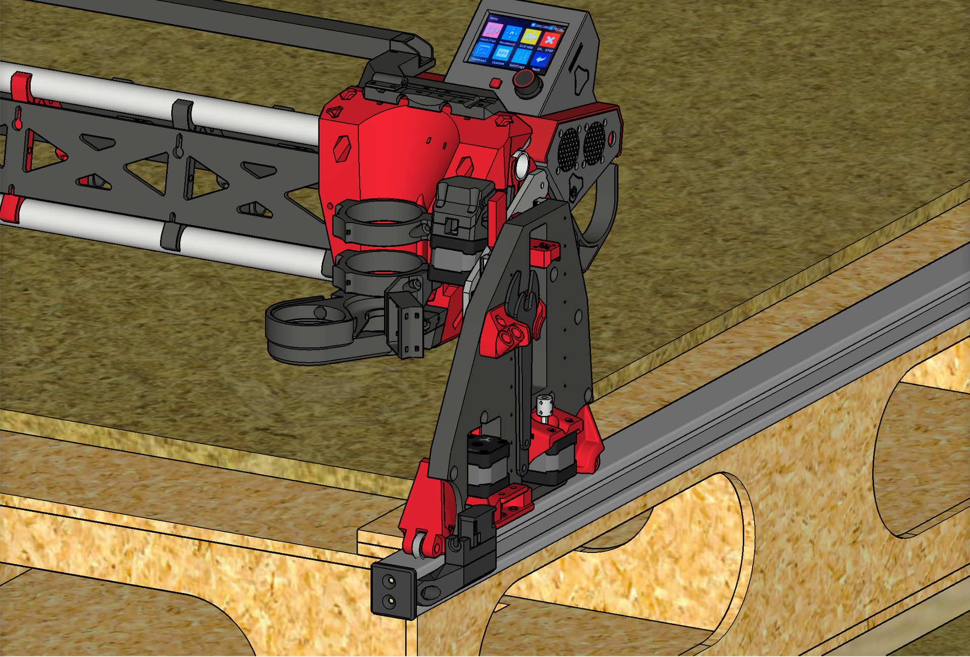
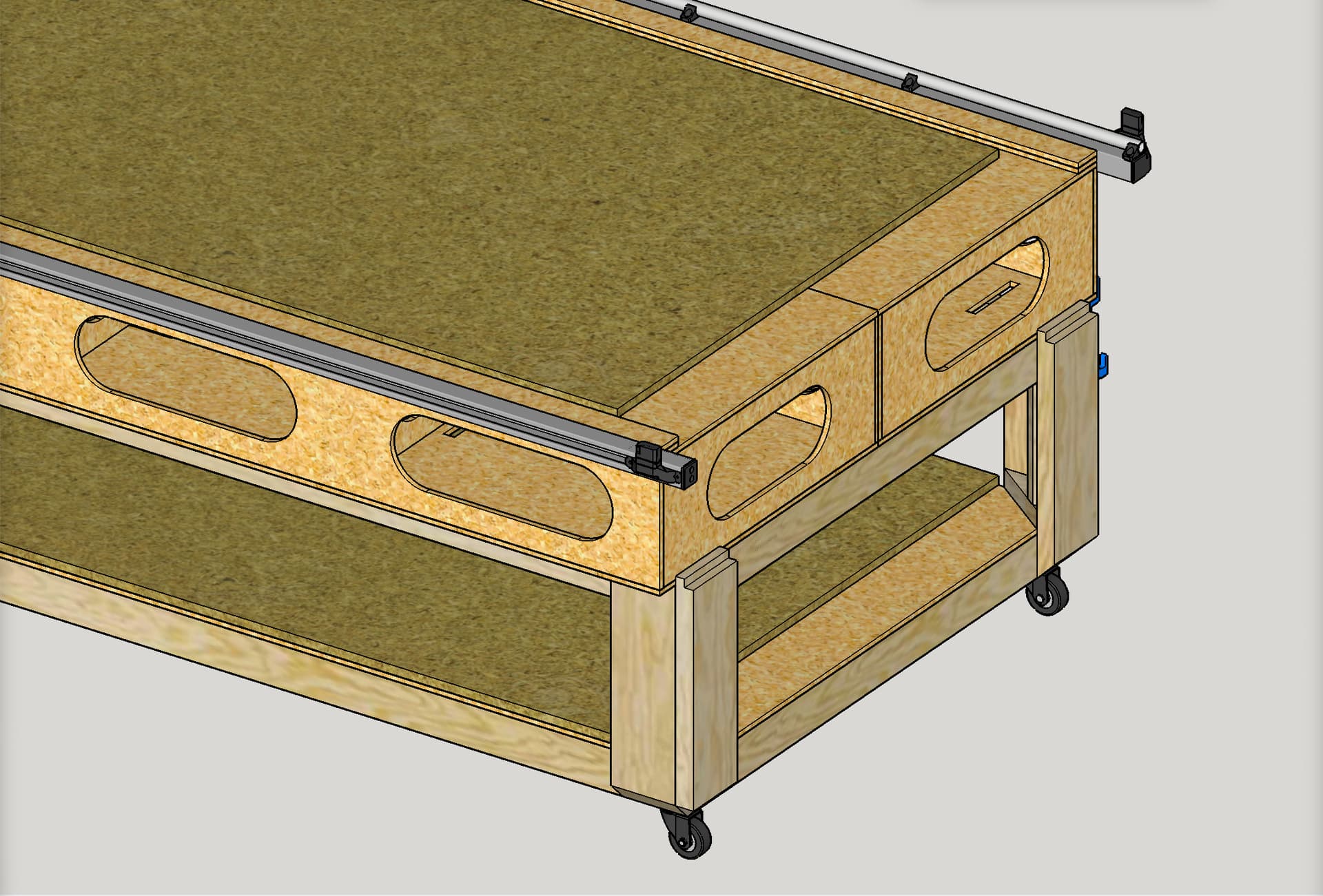
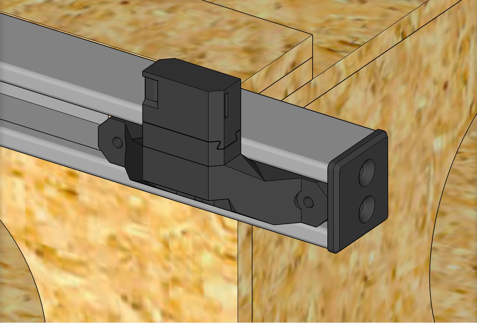
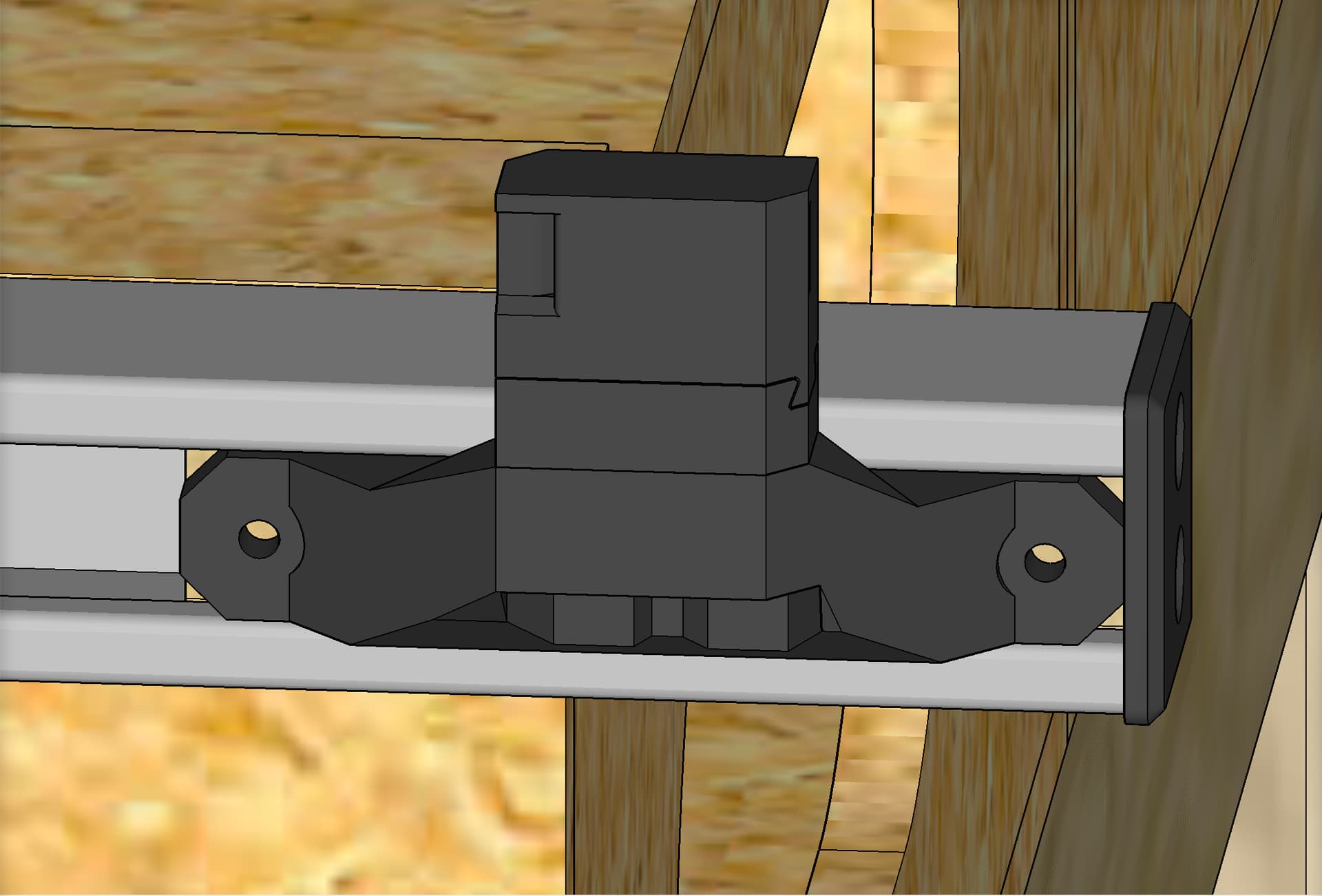
This is the “WOOD INSERTS EDITION” of “LowRider 3 CNC - table extenders to use LR2 table (with metal struts) with LR3 - endstop/tensioner supports”
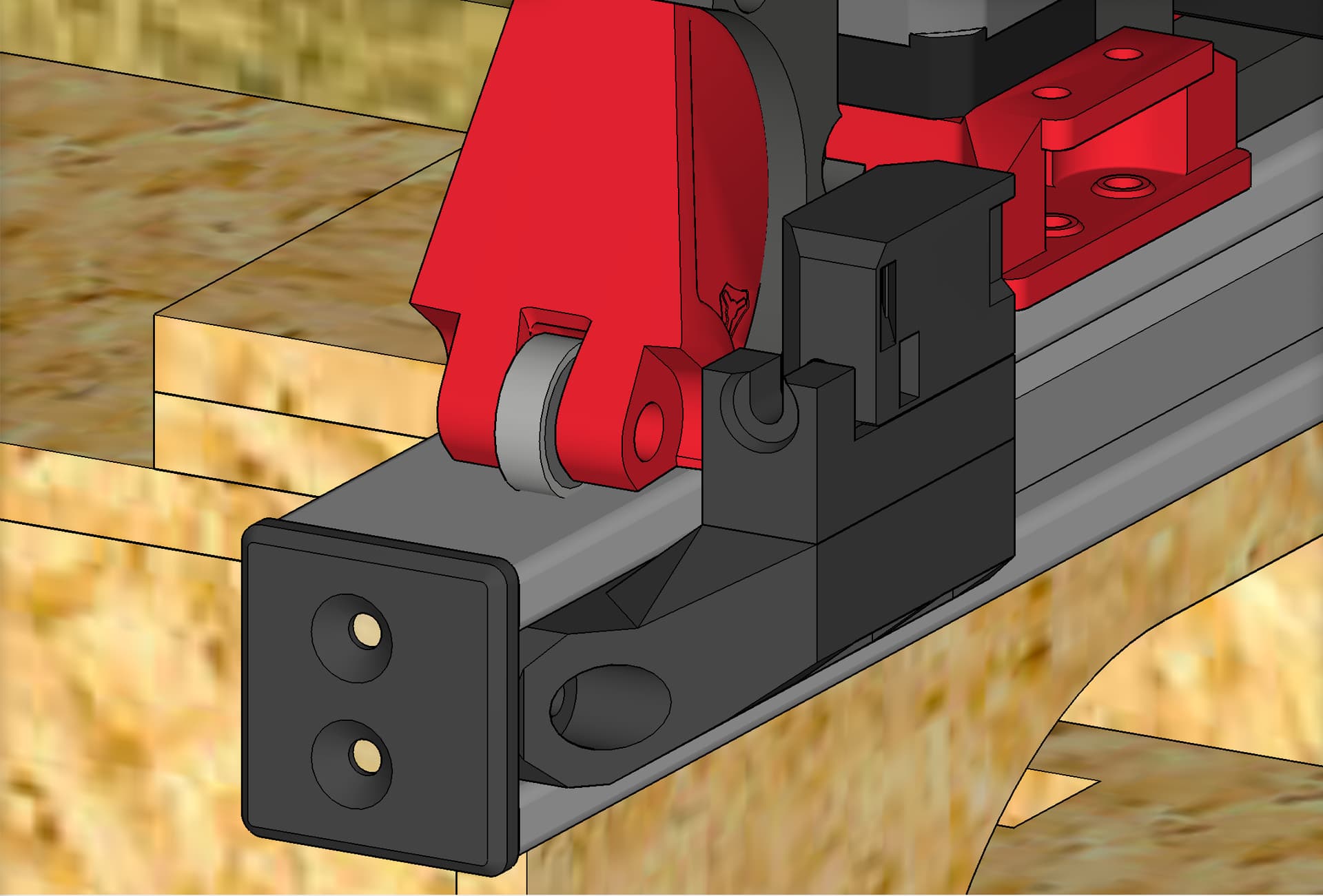
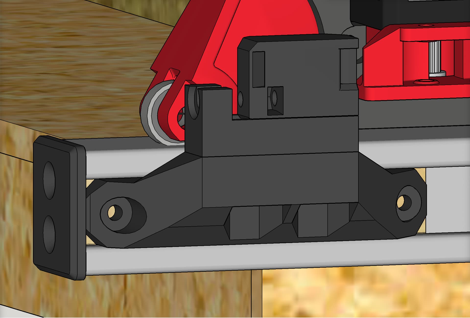
It serves the same purpose as the original design — enabling use of metal struts (aka superstrut, also aka unistrut) with LowRider v3 table. However, this edition allows using wooden inserts inside the metal strut ends, and attaching these prints to the wood, which are smaller prints than the original. This reduces how much print time is needed.
This idea for the remix was suggested by a fellow V1E maker, Spinorose on the V1E forum, and who also goes by Mask Pro here on Printables. He whipped up his own version of this remix before I got this one completed.
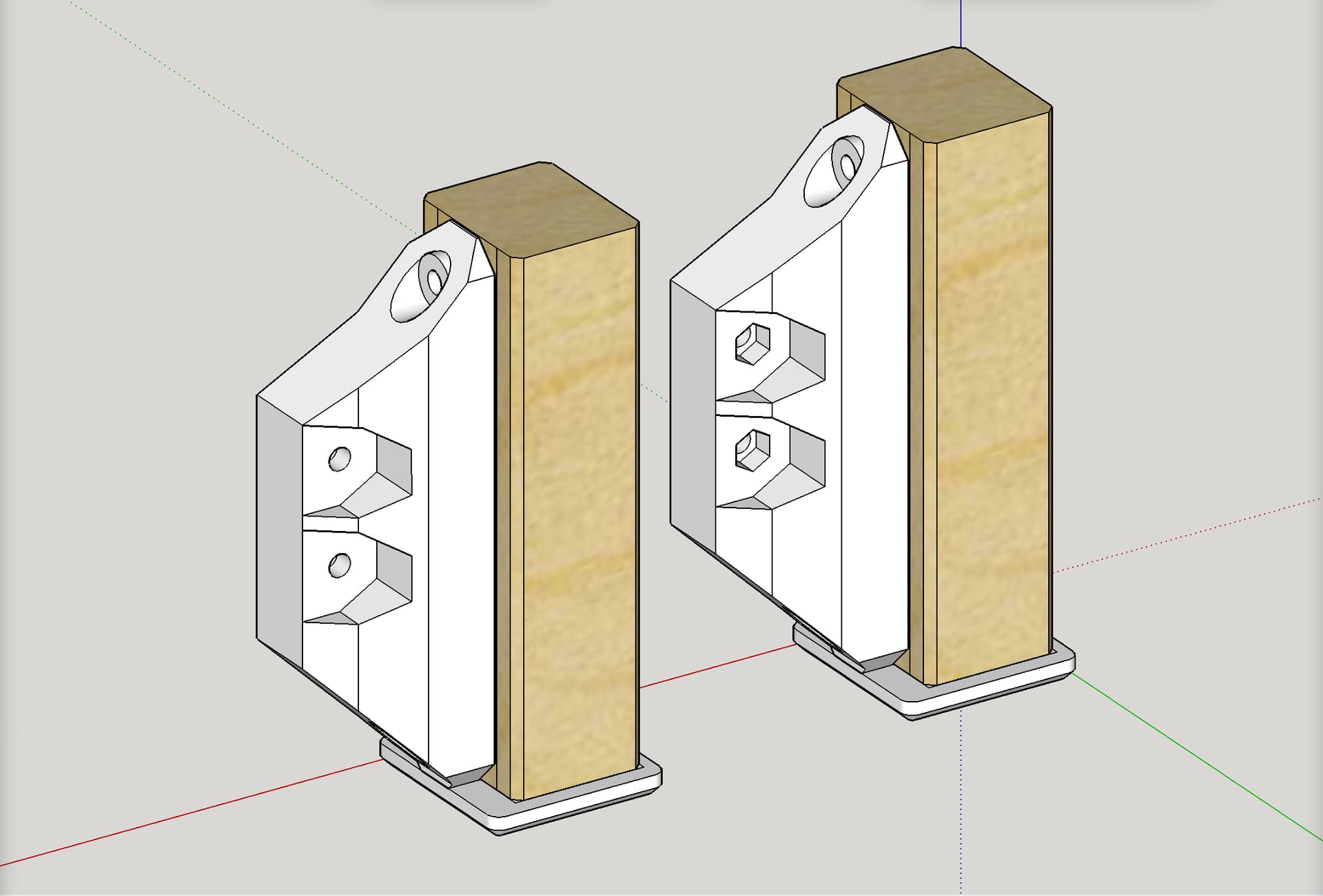
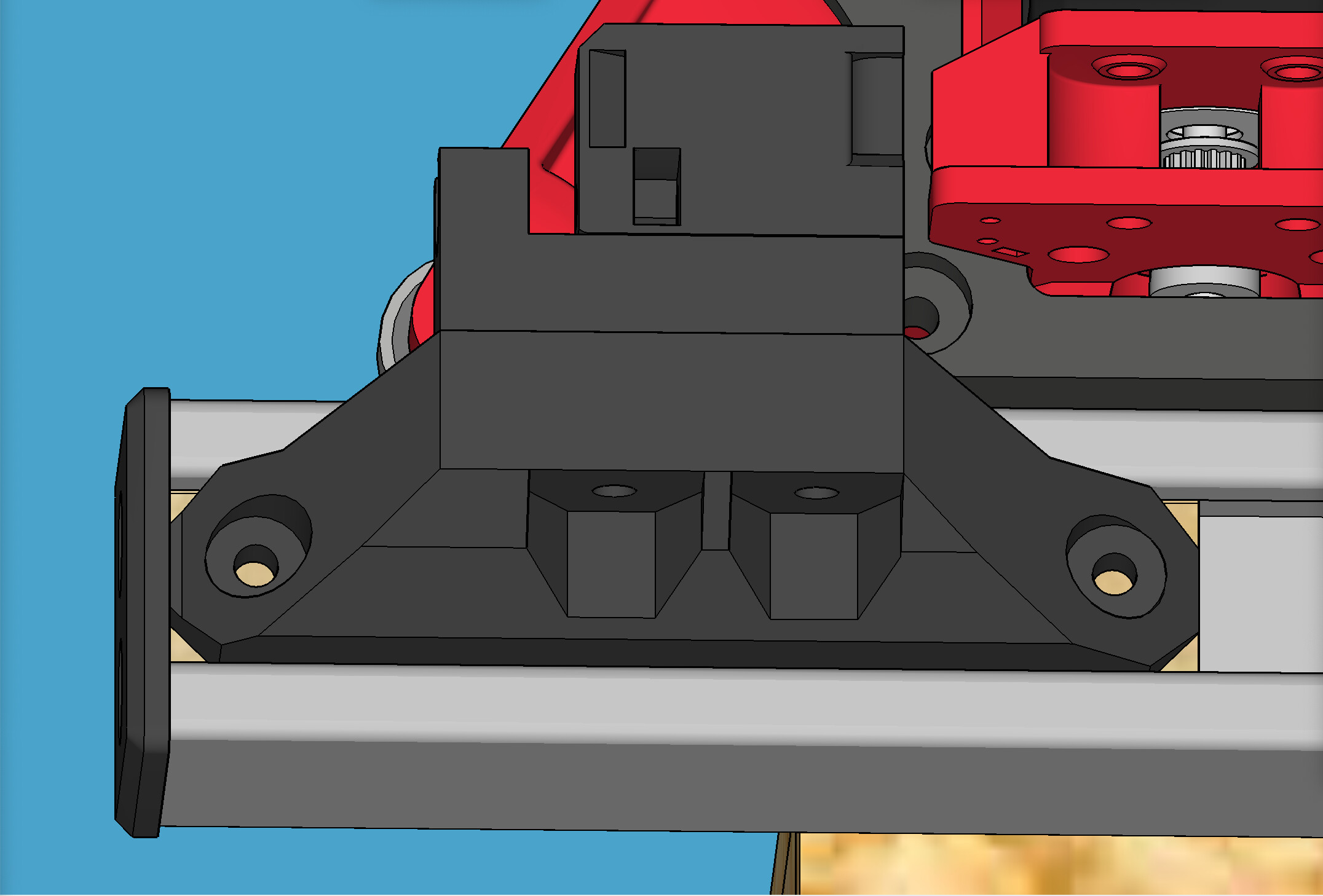
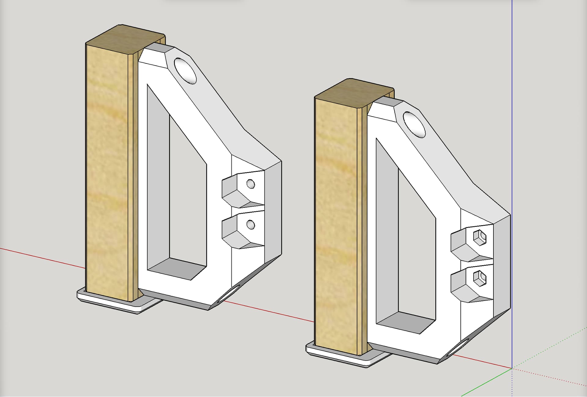
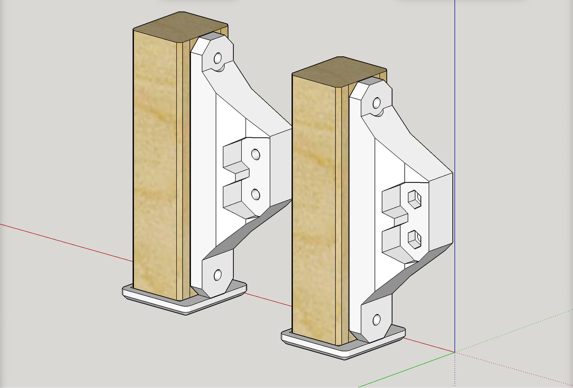
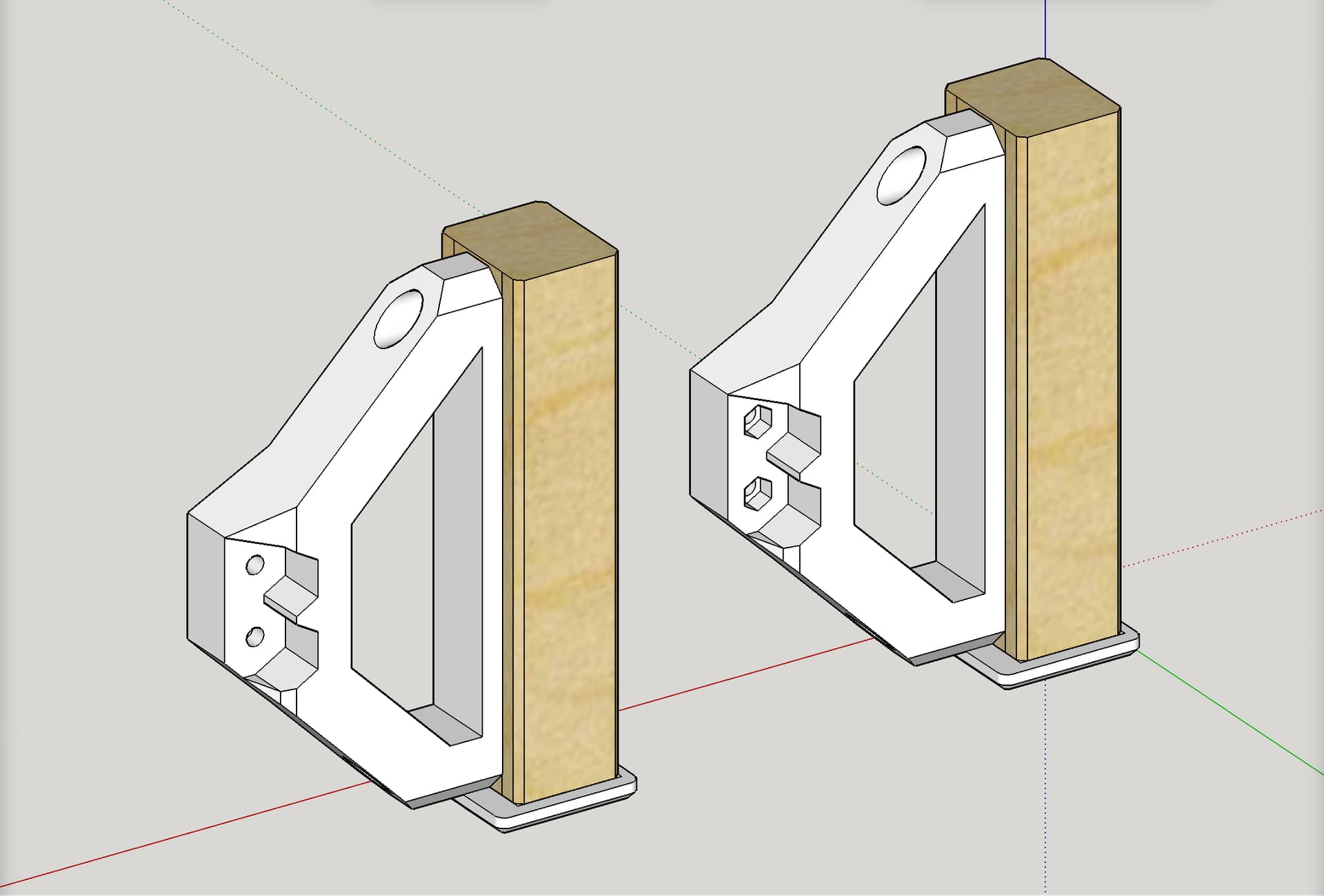
NOTE: Two versions of each printed extender are provided: one with a nut capture slot and one without. Pick your poison and print whichever you prefer. Only one or the other is needed, but not both.
ALSO NOTE: No test print has been done as this was remixed on request of someone else.
Notes on printing and assembly:
Printing:
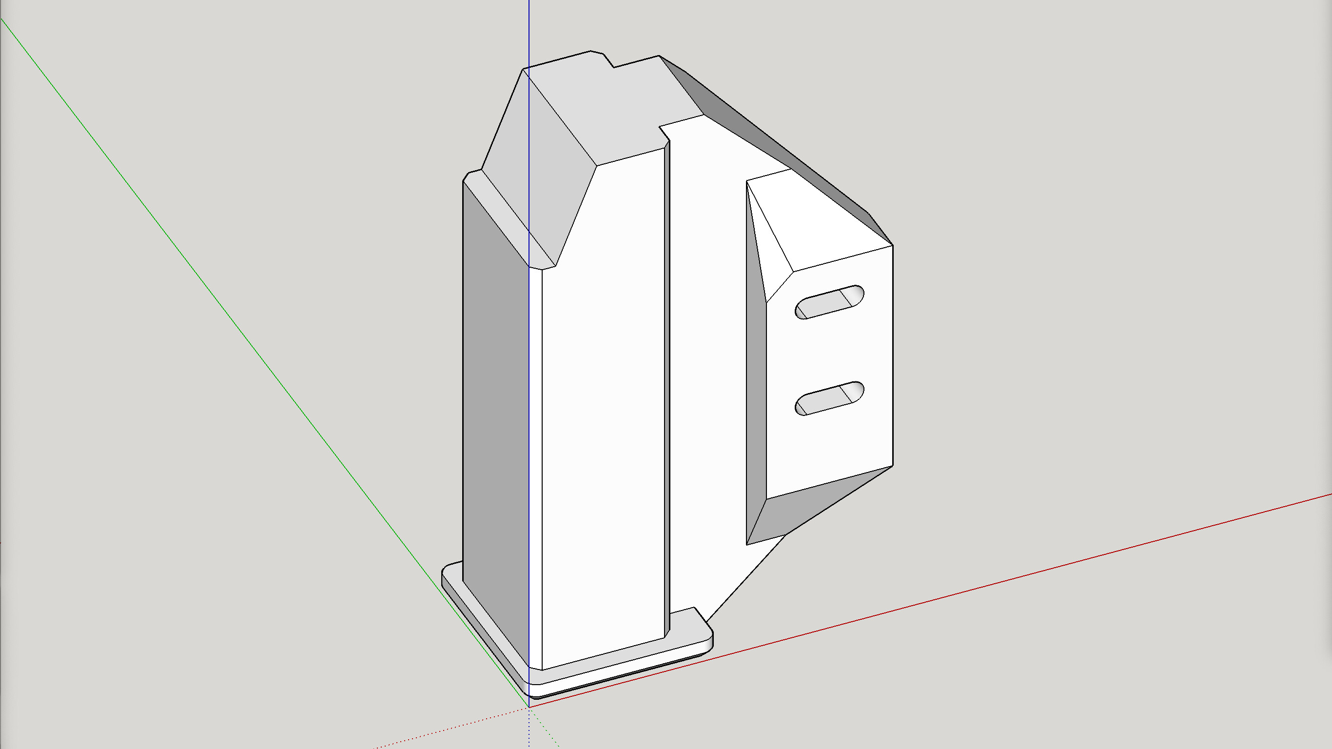
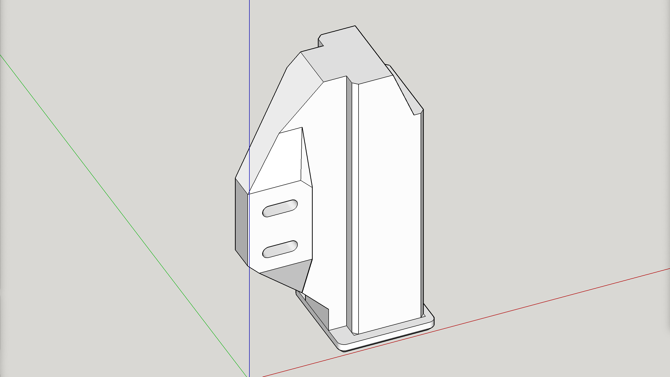
- Print as oriented
- Prints without any need of supports
- For 0.6 nozzle, suggest 2-3 walls and 30% infill.
- For 0.4 nozzle, suggest 3-4 walls and 30% infill.
- Print four (4) of the part labelled “Tip Flange”
- Print one each of the remaining four parts.
Assembly:
- Cutting wood inserts (assuming your saw blade has a full kerf width of 1/8"):
- Cut a piece of wood for the inserts, of the following dimensions:
- METRIC: 551.5 x 36.3 x 31.1 mm
- IMPERIAL: 21.72" x 1.43" x 1.224"
- It is suggested that the corners (length wise) be chamfered by about 2mm.
- Finally, cut that long piece into the four (4) inserts of the following lengths.
- Labeling them is suggested.
- Cut a piece of wood for the inserts, of the following dimensions:
| WOOD INSERT NAME | LENGTH |
|---|---|
| Rear LEFT | 145.51 mm |
| Rear RIGHT | 128.66 mm |
| Front LEFT | 145.51 mm |
| Front RIGHT | 122.32 mm |
- Drilling wood inserts
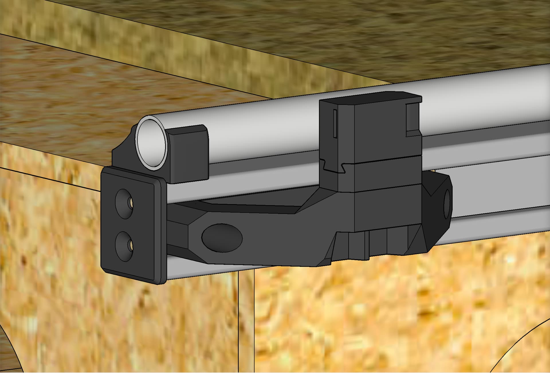
- On each of the inserts, designate one end as the outside, for attaching a “Tip Flange” part.
- Draw a line down the center of that outside end, as shown.
- Also draw a line down the center of the length on the insert’s side that will face out, as shown.
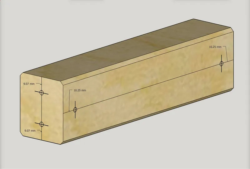
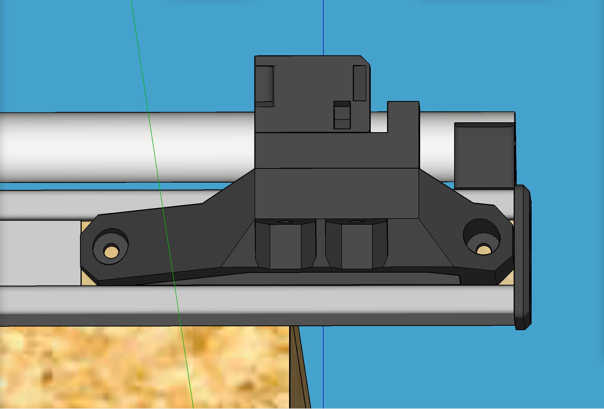
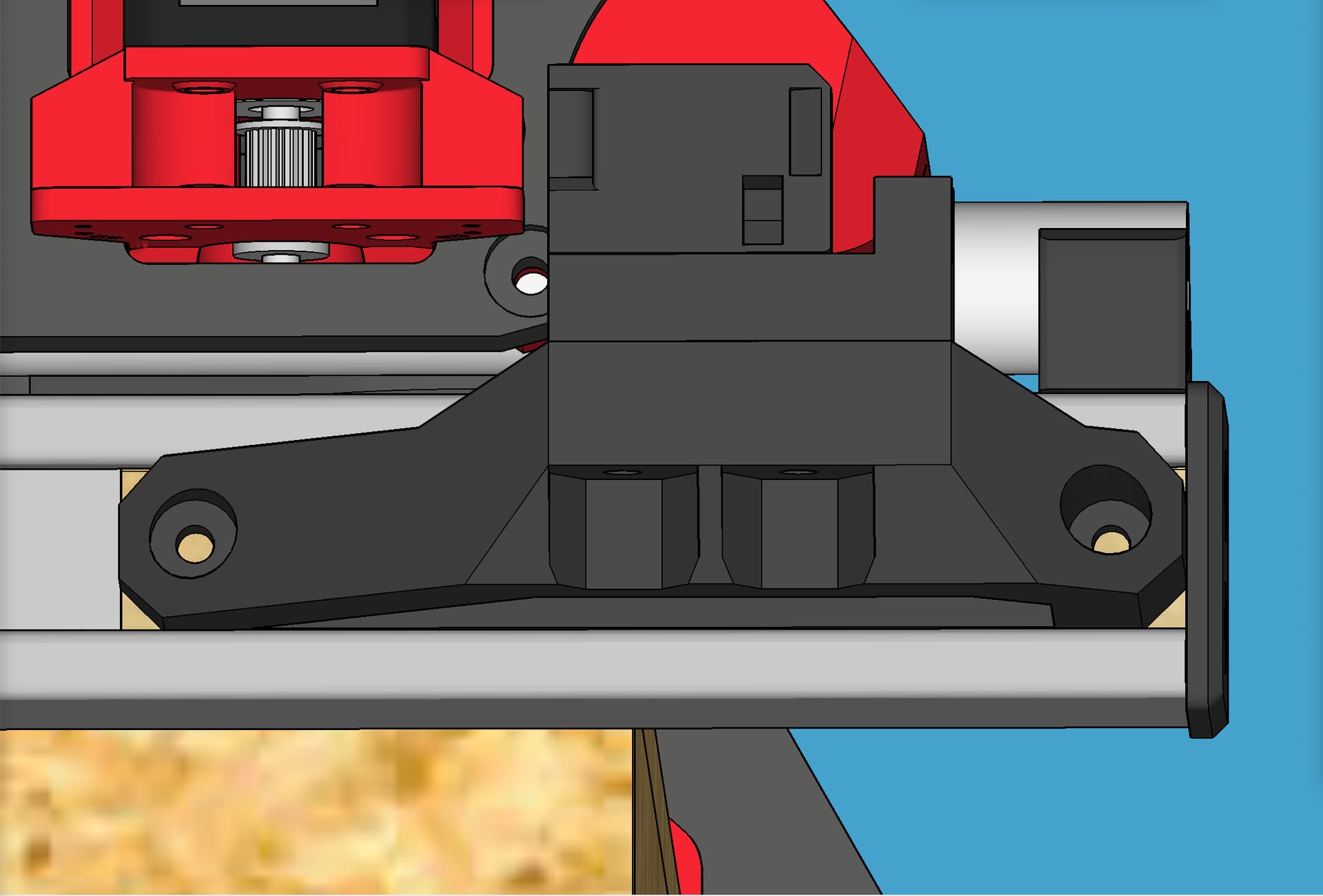
- Assuming your insert is the correct length, the screw holes on the side for mounting the printed extender part, should both be 10.25 mm from the ends, as shown. Mark the two holes. You can then verify that the hole marks are right by positioning the appropriate printed extender so its holes are centered on the center line drawn.
- Also mark two screw locations for drilling on the end. Assuming your insert is the correct height, the holes should be about 9.07mm from the top and bottom. Position a “Tip Flange” part so its holes are centered on the line on the end, and its top and bottom lips are centered on their overhang. One of the sides will have more lip overhang than the other three sides. Mark where the wood needs drilled.
- Pre-drill the two screw holes in the end, and pre-drill the two screw holes on the side.
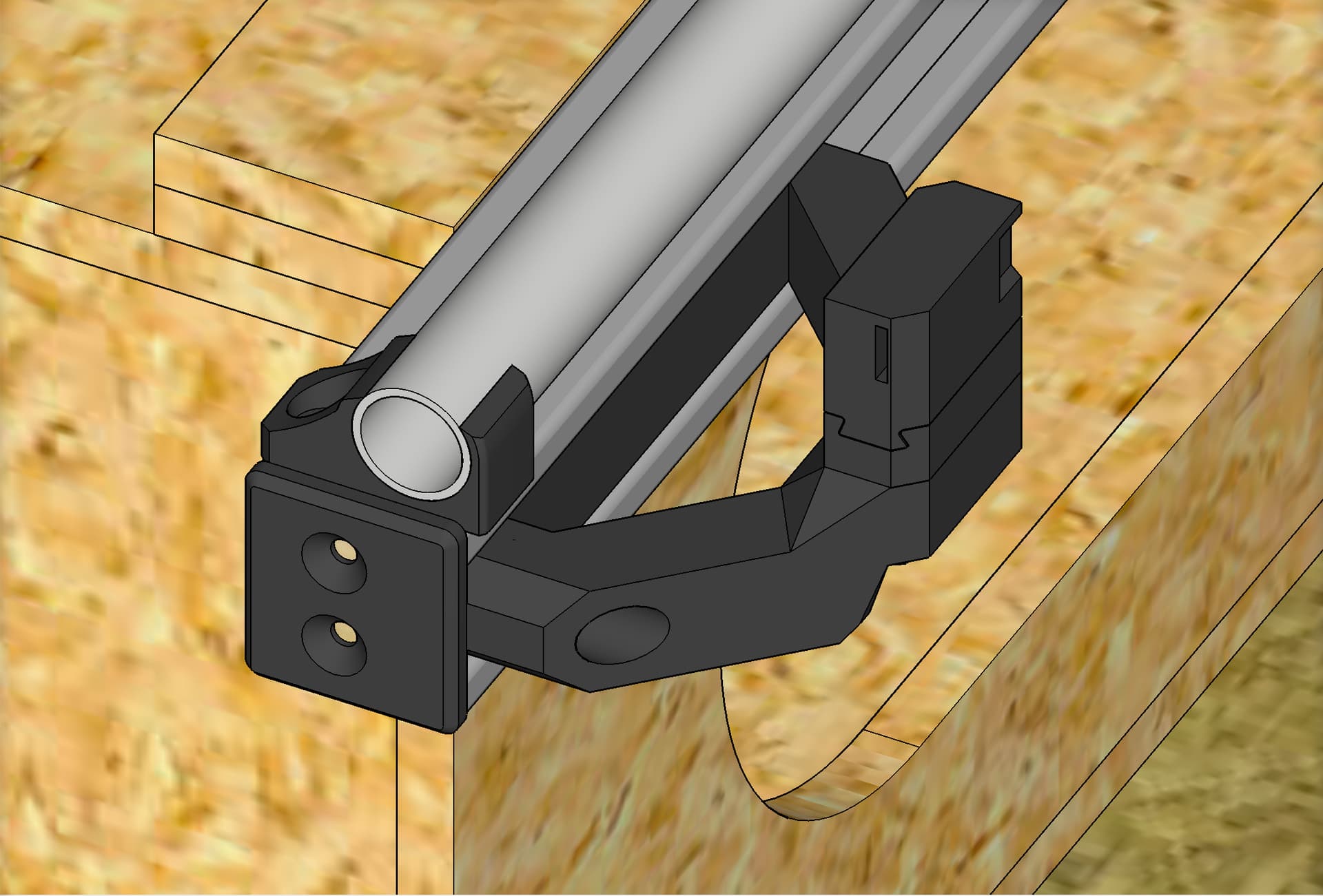
- Attach the “Tip Flange” part using two screws.
- Attach the appropriate printed extender part on the side. Repeat for all inserts.
My PayPal tip jar: https://paypal.me/design8studio
Various LowRider 3 CNC remixes:
View all my models and remixes on Printables:
*Amazon product links are affiliate links.