Correct. The calculator is coming soon and you will know exactly how much. I am working on it still.
Ryan, great job on this, I mean holy cow it’s magnificent.
Got a question.
Do the previously mentioned Heffe docs include assembly narrative along with your photos? Having rough torque specs and “don’t tighten this nut too much” helped me a lot with my LR2.
P.S. I can’t freaking wait to build this. Ordering filament and plan to fire up the printer soon!
Looks like you’ll have a spool of Prusament before you can blink! ![]() Hope you are saving up for the freight!
Hope you are saving up for the freight!
Looks good Ryan, and the LR3 Beta crew members.
Downloaded this all yesterday. Just went through the files and the docs.
The section on cutting the full length struts is blank, and there isn’t a dxf/dwg/step for them, just the temporary strut, in the files at Printables. Probably just a small oversight.
Good job, and I have use for it.
They will in the next couple days.
No more detail and CAD files are required for anything other than the two standard sizes I will provide 2’ & 4’.
Pushing the first calculator now, I would love it at least one of the beta guys can double check it on a real build. If possible, please have a good look at the belts. We might be able to get away with 7M and save some hardware kit cost.
This needs just under 5" extra table width. Remember no overhang needed so the footprint is a bit smaller in the width. The length can be shorter but comes out just about the same as the LR2 if you do not want it to overhang at all.
F5 F5
https://docs.v1engineering.com/lowrider/calculator/
I bet you guys hate watching me work in real time.
X table off in imperial I hope
Crud, I forgot about the conversion. I used millimeters after it. Sorry. Give me some time to figure that out.
Fix is building.
Strut plates added to Printables. 2’ and 4’ No more than 6.35mm (1/4") thick hardboard or equivalent is best.
Ryan, everything looks good on the calculator for my full sheet build except the required table width. I have 60.75 inches minimum. I have the printed XZ plates on currently. I don’t remember how much of a cutout there is in the printed plate for the linear rail blocks, but when I swap to the 1/4" aluminum, it will probably fit on a 60.5" table.
I have a note on the calculator and the default is set for the printed part XZ plate. The width is set for the outer edge of the newest belt mounts, or the outer edge of the Newest Y drive. (the build actually sits 3mm wider than that).
I missed that setting on the calculator. Means my build is perfect!
Rad!
There are so many details to this one. It is fun but I am still barely scratching the surface. I think most of the major stuff is done now I just need to keep filling in details.
C’mon! I am just about to start getting my lowrider 2 working after a wait of over a year. Now you have to come out with a new one? Geez. Now the dilemma… finish building my L2 (just leveling table and flattening spoilboard, then learning how to use), or upgrade to a L3. Hmmm. Decisions, decisions.
Note, I have a flip up table on the side of my garage where the top flips towards the wall, so the L3 might be better.
I think the votes are leaning hard towards finishing any in progress LR2’s and using them to cut all the flat parts for the LR3. That leaves you with some hard learning on the previous machine, better size choices for the new one, and an upgraded less expensive LR3 from the get go, and it save a bunch of assembly and disassembly steps…
That makes sense. In the mean time, I’ll start printing up the 3D printed parts and looking at the differences more.
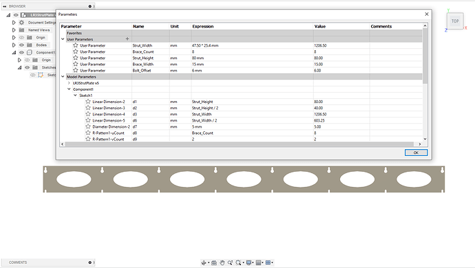
I know Ryan’s CAD is out there too, but I also did a parameterized version in Fusion360
No V1 logo ![]() and the fancy diagonal braces are gone, but it will adapt for any (reasonable) number of brace pieces (I’ve tested with anywhere from 3 to 13) and about any beam length that you might want.
and the fancy diagonal braces are gone, but it will adapt for any (reasonable) number of brace pieces (I’ve tested with anywhere from 3 to 13) and about any beam length that you might want.
Sweet!
