Download link on Printables:
Printables
The following is a copy and paste from the Printables description:
If your LowRider 3 CNC takes the normal approach, with a vac hose from below hanging on hose hangers, this listing has nothing for you.
If like me, your LowRider 3 CNC has a vac hose from above, and uses a drag chain, then you might find benefit here.
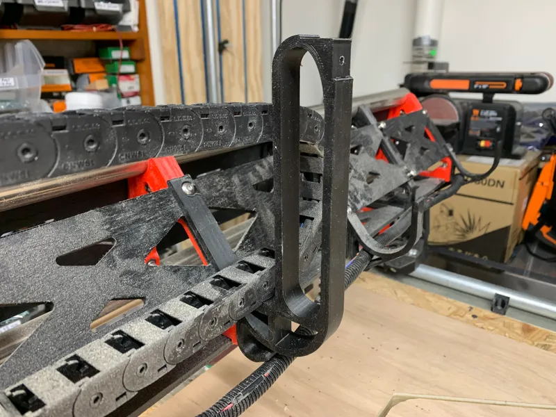
I have a shop-wide dust collection system, with 4" pipe, which has a drop down to my LowRider, and on the way down it gets tapered from 4" to 2.5" hose. I use a small drag chain on the LowRider, mounted on a modified version of the hose hangers.
This works great. However, in rare instances on 4’x8’ full-sheet cut jobs (which run the gamut on my table) the core can carry the hose into a position that risks it getting tangled underneath the drag chain. This can foul a cut job!
I seriously considered manufacturing a “boom arm” to constrain the hose’s movement, but I decided this low-tech approach would be easier, faster, and less expensive.
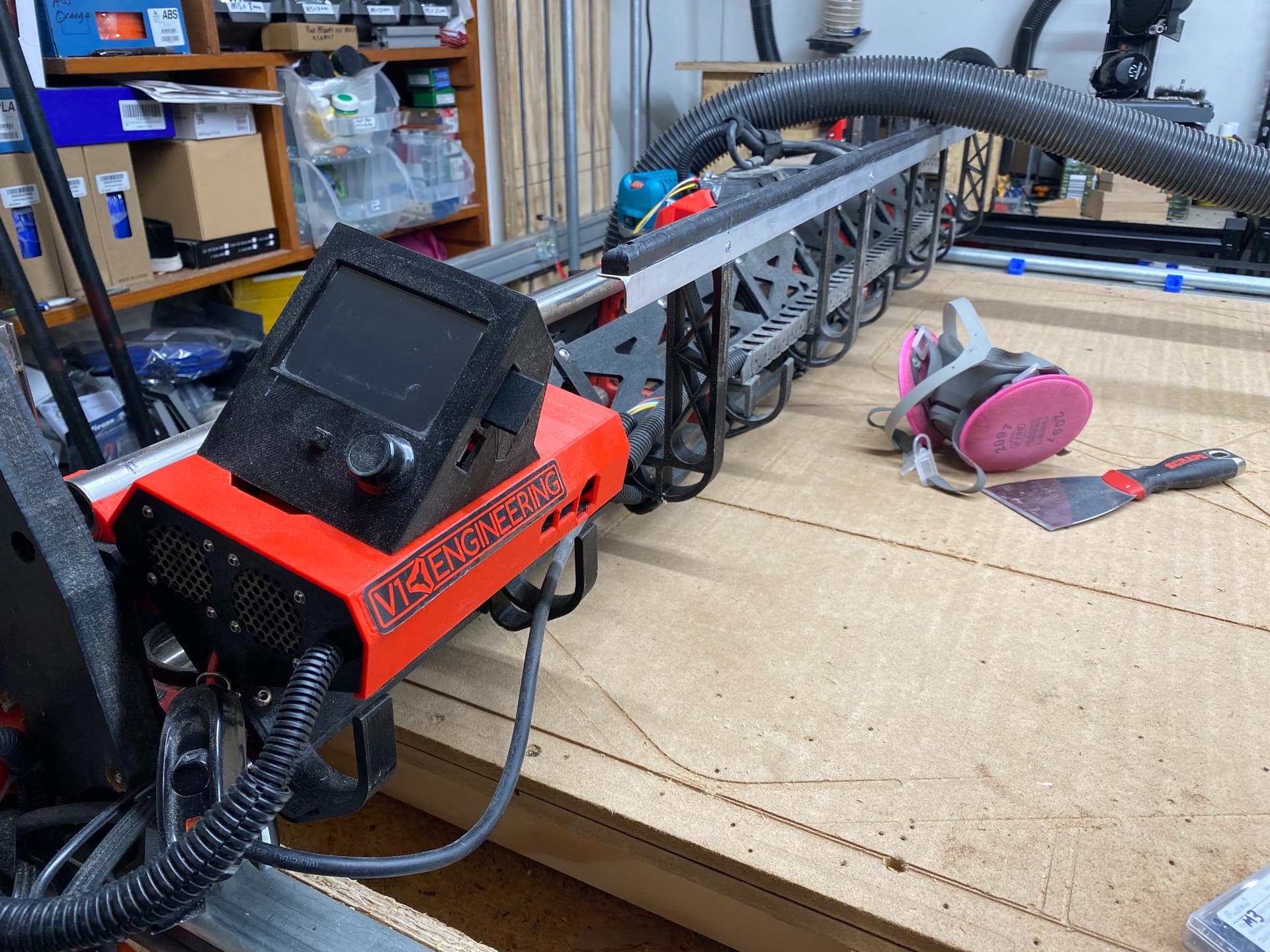
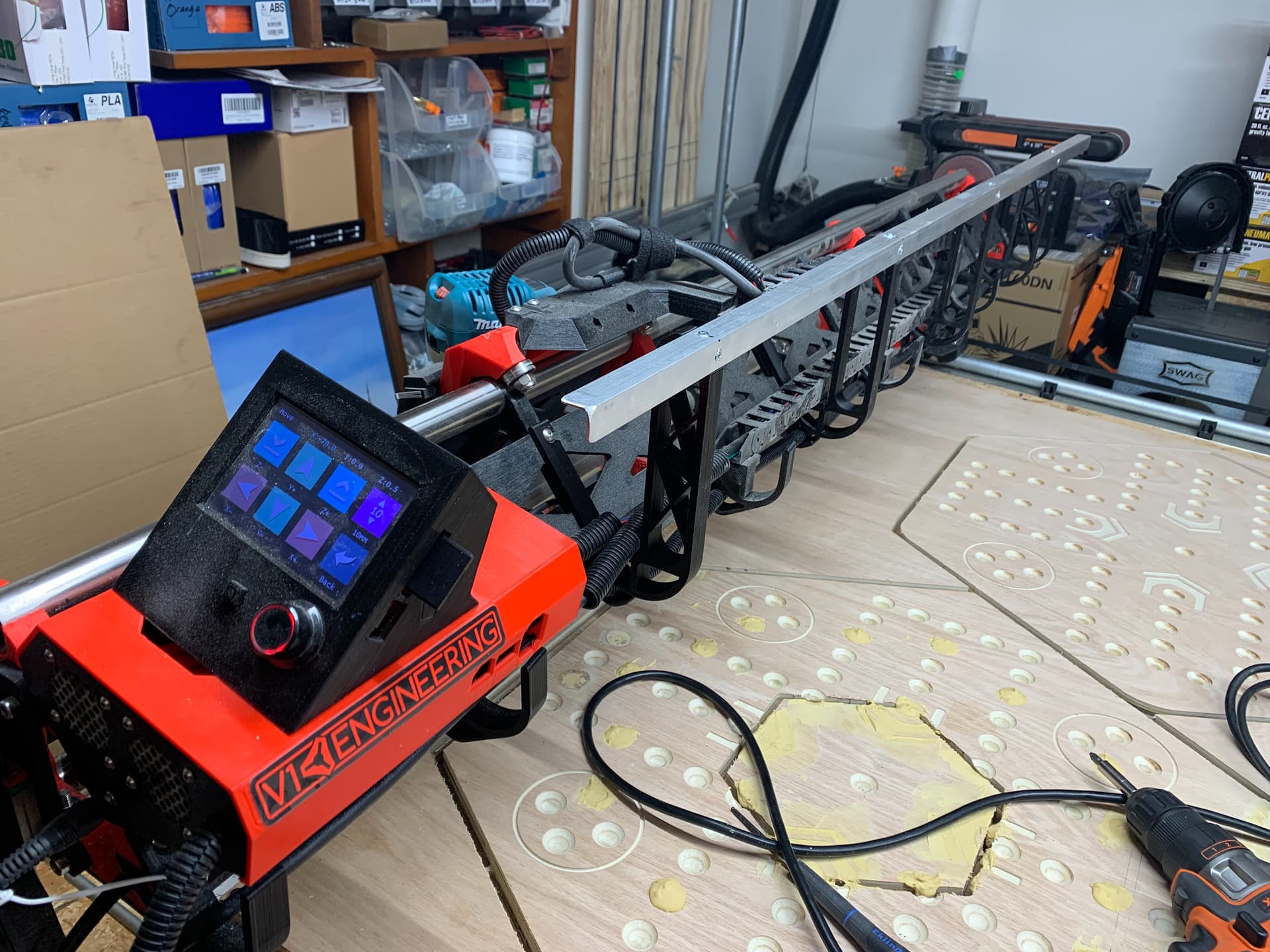
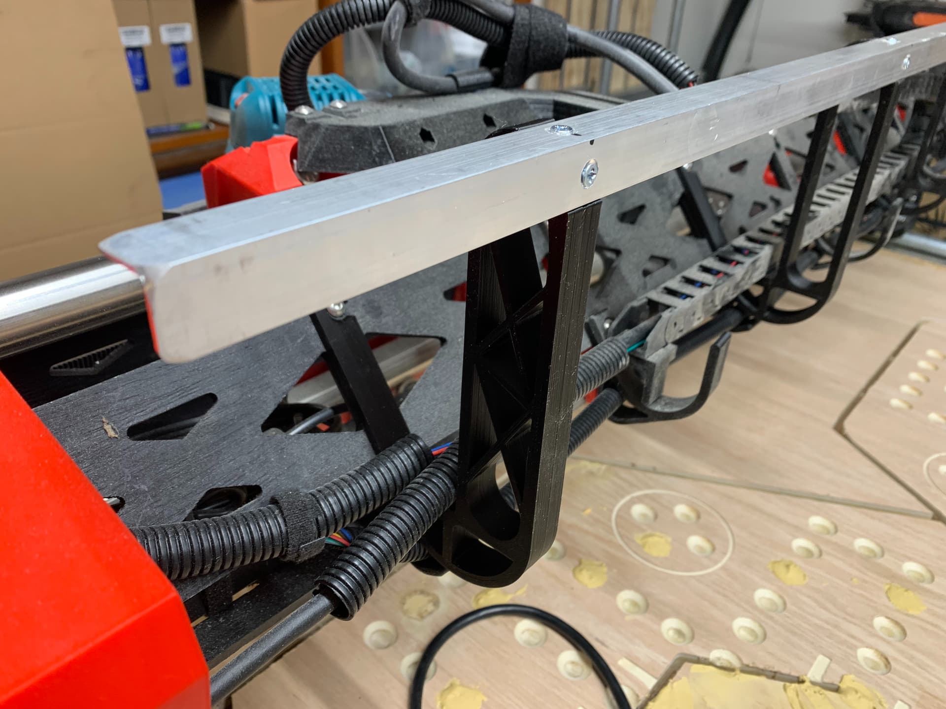
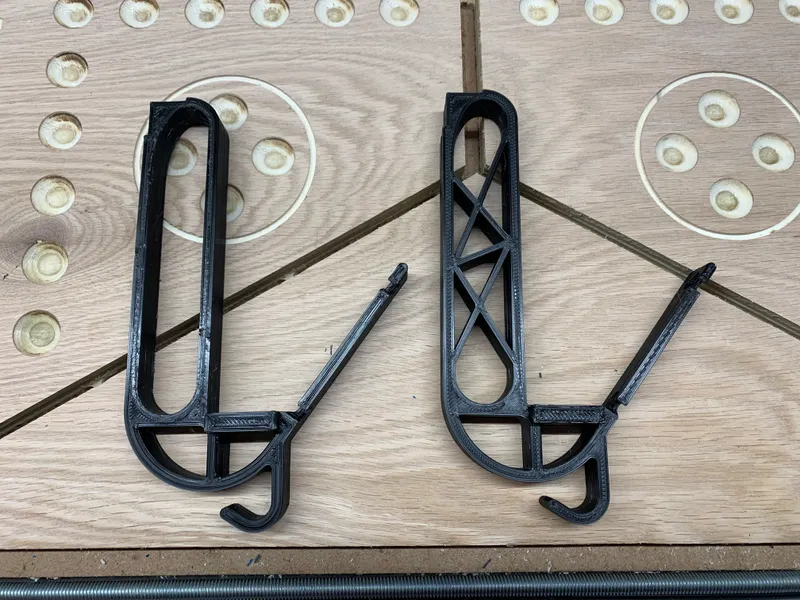
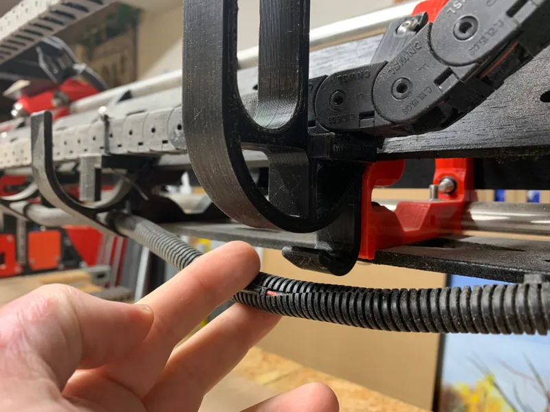
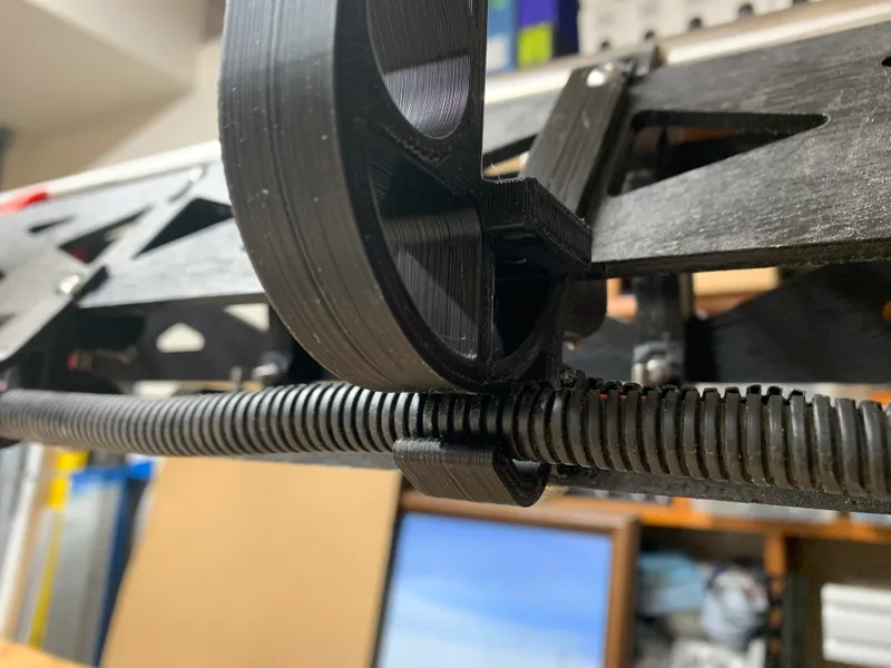
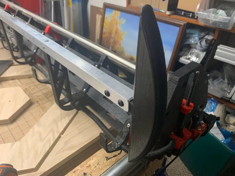
I’ve suspended a length of affordable aluminum angle brace, ¾" x ¾" x ¹⁄₁₆", held in place by a set of a printed part that serves for triple duty: it can serve as a lower mount for the drag chain, and for a support for areas where the drag chain lays but is not mounted, and in tandem with other braces like it, it holds up the aluminum angle brace that shields the drag chain from the vac hose. I installed one of them in place of every third hose hanger, for a total of 4. I named this part:
- LR3 CABLE CHAIN MOUNT (lower) NEW w SHIELD
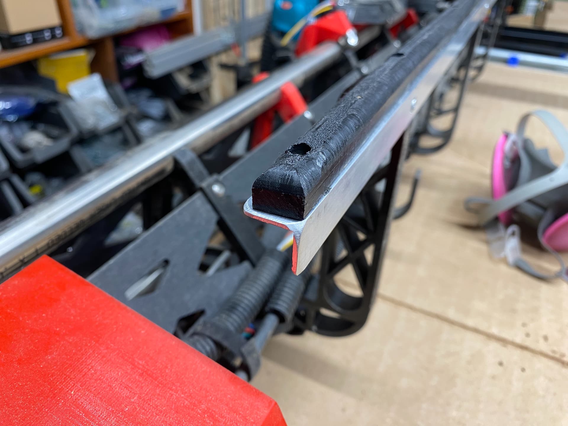
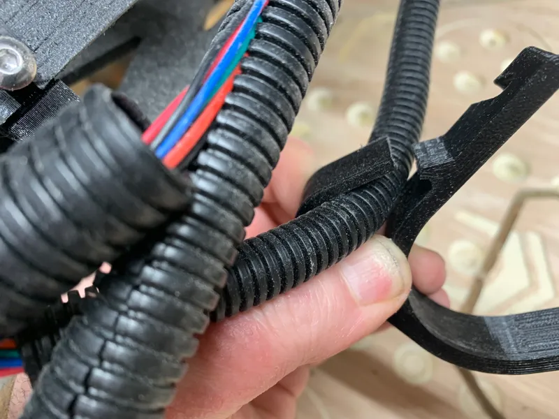
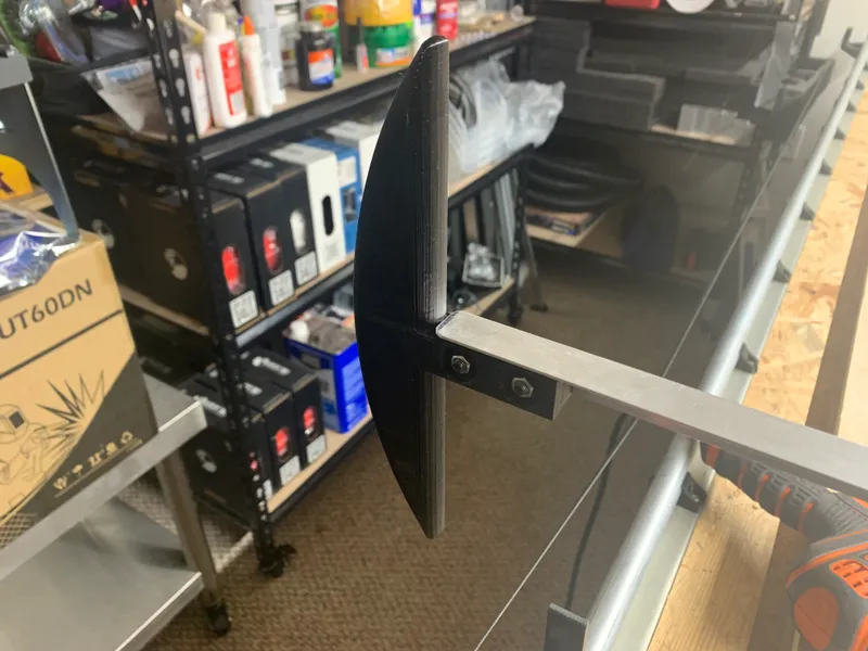
The above is enough protection for almost all instances, however, on full-sheet cut jobs, there is a place on the far left edge where the core can carry the hose into a coiled path that slips off the edge of the aluminum angle brace, and it can get hooked under it on the way back. To prevent that, I added a printed “flange” to the end of the aluminum. It gently keeps the vac hose on top of the shield, where it can slide along harmlessly. I named this part:
- LR3 Drag Chain Shield End Flange
Printing
- Prints as oriented
- Prints without supports
- For the LR3 CABLE CHAIN MOUNT (lower) NEW w SHIELD:
- For 0.6 nozzles I recommend 3 walls and 30% infill, 0.3 layer height, 0.6 wall width.
- For 0.4 nozzles I recommend 4 walls and 30% infill. Or you can have the 0.4 nozzle emulate a 0.6 by using 0.3 layer height, and 0.6 wall width, and do 3 perimeter walls.
- For the LR3 Drag Chain Shield End Flange:
- For 0.6 nozzles I recommend 2 walls and 20% infill, 0.3 layer height, 0.6 wall width.
- For 0.4 nozzles I recommend 3 walls and 20% infill. Or you can have the 0.4 nozzle emulate a 0.6 by using 0.3 layer height, and 0.6 wall width, and do 2 perimeter walls.
Assembly/installation
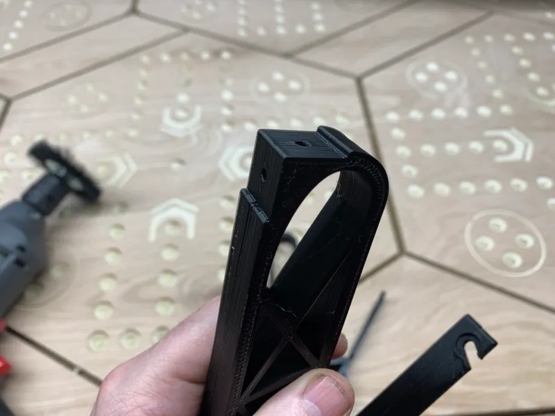
Re. the mount parts, I made an open version first, then a revision with webbing to brace it. I’m only uploading the one with bracing. If you need the open version for some reason, let me know.
The mount parts attach to the gantry by use of both the upper and lower screws that hold the strut plates. This is unlike the normal hose hangers that only use the lower screw.
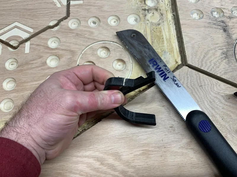
I designed the mount part so there would be no need to undo wiring and redo it, merely because of some of the wires having been routed through the lower socket hole on the bottom of the earlier remix of the hose hangers. I loathe messing with the wiring once it’s working right. So, I used a dove-cut pull saw (IRWIN Dovetail Saw, 7-1/4-Inch - 213104) to slice through the lower socket on the old hose hanger parts (on every third one from my start point), and pried the gaps open enough to slip the wires out.
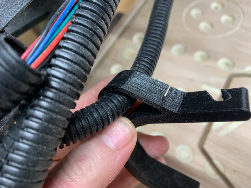
My new part has three support structure paths instead of two, so it could afford to leave an opening into the bottom area, so it’s now an open hook instead of a closed up hole. By squeezing the wiring sleeve a bit, I was able to insert my wiring (the wires that needed that lower pathway) into the new mount parts.
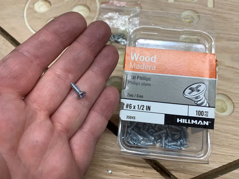
The screw holes on the printed mount parts, for holding the aluminum angle brace, are approximately M3 size x about 6mm deep, but I used #6 x ½" wood screws, tapered, with flat head (made for a countersunk install with the top being flush with the aluminum).
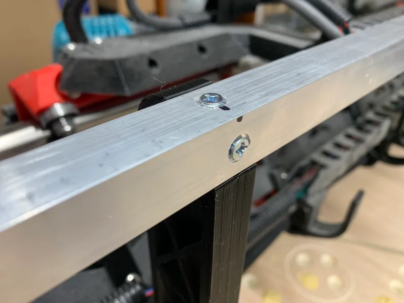
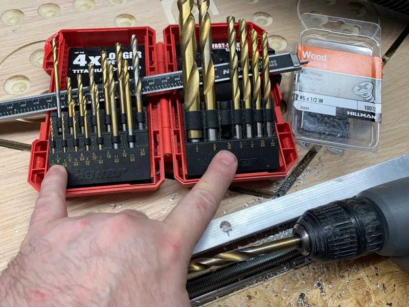
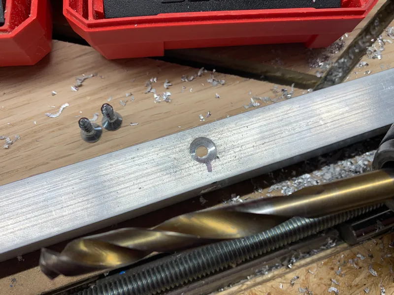
For drilling the holes in the aluminum, the placement of the holes is centered on the inside faces of the angle brace aluminum. Once you get them placed and drilled, you can use a larger drill bit to get the counterbore for countersinking the screws, if you desire that.
To drill the smaller holes for the screws, I used a ⅛" drill bit. To counterbore them for countersinking, I used a ⁵⁄₁₆" bit.
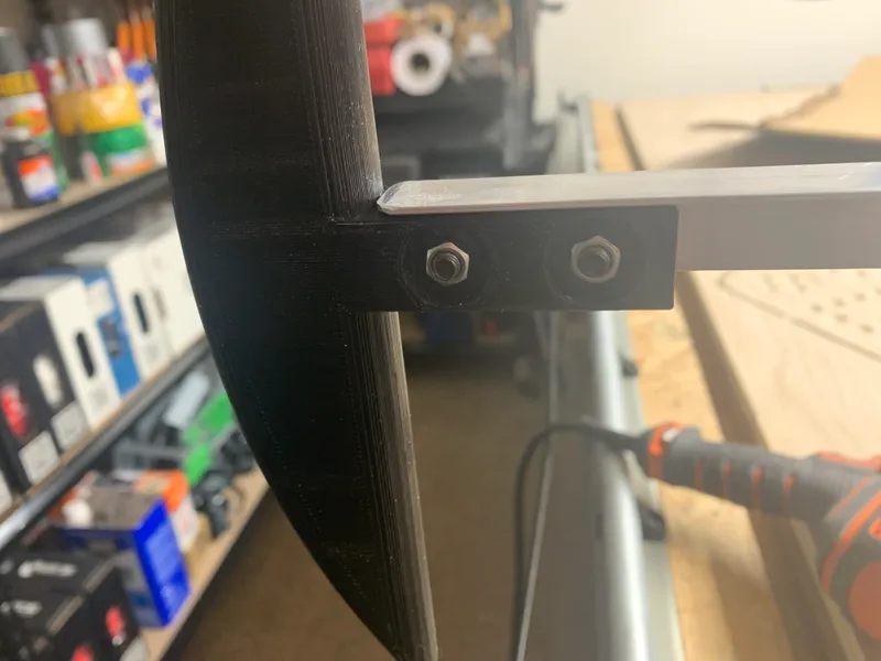
The holes in the printed flange part, for attaching it to the aluminum, are M5, and they pass all the way through, with wells on the other side for nuts, giving enough room to grip the nuts with either a socket or needle nose pliers.
Re. screws for mounting the flange, I used two (2) M5x20mm screws. I used regular nuts, although you could use nylock if you wish.
For drilling hole size, I used a ¹³⁄₆₄" drill bit. A ³⁄₁₆" bit could also be used. The first hole is centered 12.5mm from the end of the aluminum. The second hole is 25mm from the first, center to center.
My PayPal tip jar: https://paypal.me/design8studio
Various LowRider 3 CNC remixes:
View all my models and remixes on Printables:
*Amazon product links are affiliate links.