LowRider 2 - Long time coming - (Australia)

And in today’s news:

> Your order’s in!
> When your order has finished processing, we’ll email info to you
> You should get it by 5 Nov.

But in truth there’s a lot I can be doing in the meantime, including having a week roaming around in the camper! :smiley:

1 Like

Now where was I?

Oh that’s right, I went for a bit of a drive for a week and when I got home I had crimpers, connectors and a yellow paint marker pen. I also figured there’s no point in having a “no budget” build if I can’t afford a couple of dollars for a paint marker.

“No budget” doesn’t mean I’m spending indiscriminately, it just means I don’t have a budget! :shushing_face:

I guess I should try to figure out where I was and work out how to make noises with this thing soon, after all I’m currently one year into this build, minus 16 days. Can I avoid pushing it beyond twelve months?

Stay tuned for the next exciting episode!

3 Likes

My definition of a “no budget” build would have me limited to parts and materials I already had on hand.

1 Like

That’s a good call Tom. So I have a no budget table and I don’t have a budget for the rest! :smiley:

I’m envious of your unlimited budget for at least part of your build.

1 Like

Well Tom, by your “no budget” definition, and in the spirit of Dolly Parton’s famous quote - “it costs a lot of money to look this cheap”, I had some automotive loom fleece tape lying around, leftover from my camper build, and I guess I’m about to find out why no one seems to use it in this environment! :rofl: :rofl:

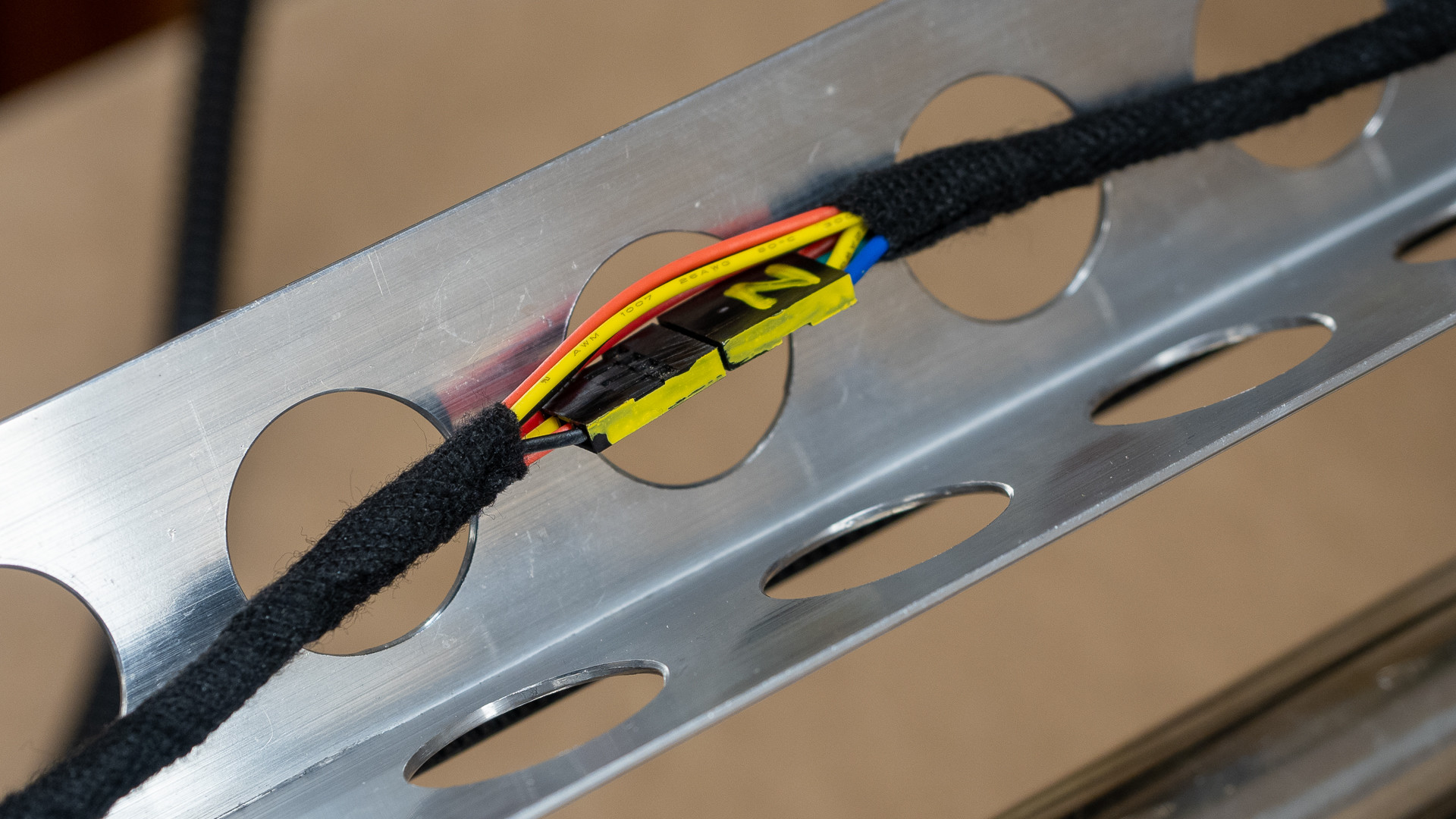
By some miracle - everything moves when I tell it to, and only one connection needed reversing! I’ve marked the sides of all the dupont connectors with yellow so I know which way to put them back during final assembly, which would be happening now if I wasn’t reporting in!

5 Likes

That looks nice and clean, and easy to troubleshoot the connection. I had an old spool of 6-conductor shielded cable when I built mine, so I didn’t need to do much of my own bundling. I did add some braided sleeve around the stepper motor and end stop leads where they made the turn to go into the conduits. All my X and Y connections are buried inside the conduit and kapton-taped together. The Z connections are taped too, and these are velcroed in place on either side of the joint in hopes of minimizing any flex of the connection itself. I haven’t had any work themselves loose yet (fingers crossed).

1 Like

Well there’s today’s learning done! :smiley: I hope I don’t need the heat resistant properties for my loom tape in any of the places it’s going, if I do it probably means I didn’t get something quite right.

2 Likes

It’s a bit early to be smug, because I haven’t chopped the ends going into the board yet, so that one last bit of spaghetti will have to wait till tomorrow, but I have to say I am a bit pleased with how tidy it is. In fact I’m so happy with it I thought I’d share a couple of preliminary pics. :smiley:

Although it’s the longest route to completion by far, I’m testing each set of pins as I go. I figured if there was a problem with one connection it would take a lot more time to trouble shoot than it does to turn the whole shebang on, move the axis in question a millimetre or two then turn it off and get on with the next one. So far so good.

2 Likes

I only use kapton for this because I got a roll a while back when building 3D printer got ends from scratch and haven’t managed to use it all up yet. Scotch tape would probably be enough to keep the ends from sliding apart accidentally.

2 Likes

Today could be described as “interesting” I suppose.

I have many questions to ask regarding the “700 (was 611) plate” and will save most of those for the next round - actually having the thing working may well answer them. For now, I have decided to use my something a bit less than 1 1/2" shopvac hose, mostly because it’s new and shiny looking, but also because with a new adapter it fits exactly onto @vicious1 Ryan’s stock parts.

Not much more than a year ago, before I had a 3D printer, at a time where I had never drawn anything on a computer, I would have simply grabbed an PET old soft-drink (soda) or water bottle and made an adapter by heat shrinking it. Sometime this afternoon, brain completely disengaged by way too much Mexican F1 Grand Prix at three o’clock in the morning, I thought I’d just do that as a temporary measure.

NOTE - PLA does indeed assume vastly different shapes if you heat it to the temperature that is necessary to make PET shrink. Thankfully with a bit of judicious patting and tooling, damage was minimal!

I understand completely why the vac inlet is oval with a flat spot on it, but sadly my vac attachment is round and quite rigid, and in less than the time it would have taken to search Thingiverse, I had a quite tidy connection drawn and printed. It’s vaguely complicated but it will do for now.

With that sorted it was time to mount the final version of the board and screen brackets and while I had allowed half a millimetre clearance between the back of the screen and my fancy pipe plugs, I chickened out and made a couple of spacers to prevent any future issues.

With only the board end of the wiring loom to go (twelve more pins by my count) I removed and adjusted the grub screws on the couplers and pulleys and gave them a generous splash of locktite before fitting the cover over the stepper.

About now I’m wondering just how temporary those temporary MDF flat bits are, but that’s where I’m up to. It can’t be long now. Can it?

5 Likes

I’m not quite up to @vicious1 's wiring tidiness, but I aspire to be and I’m quite happy to leave a bit of scope for improvement. I can’t be sure but I might have the X and Y axes swapped - I get a bit confused about that standing on the side of the thing! If I do I’ll get a bit more practice I guess.

In my struggles not to make “improvements” until I at least get the machine operating, I haven’t found any way of tidying up the cabling on the Y axis. Everyone seems to just let it drop onto the floor which I suppose is OK if you a) have tiny feet and b) are not a clumsy old oaf prone to tripping and catching up on things.

I briefly considered rigging a drag chain, and this bracket was the beginning of that, but it evolved into something much simpler. The intention is that the router cable will run along side the power cord, the bracket should be strong enough to securely hold the power plug connection for the router (If it works I might even build one incorporating a socket). By mounting the power supply and running the router cable to the centre of the table opposite, everything should be tidy and out of the way - if I don’t like the sag, I’m thinking I might just tension the cable mid-span with a bit of shock cord.

There’s plenty still to do, but I’m retired so I probably won’t have time to work on it for a few days, so that’s the update for now.

4 Likes

Back into it on and off - with seven days before the first anniversary of construction commencing and apart from having a lot of other stuff gettting in the way, I’m almost confident that we’ll have that first drawing done by then.

But first let’s have a great big whine about how badly designed that 611 plate is! :wink:

Somewhere in the course of construction, someone, somewhere mentioned in another thread that Loctite is a good thing to have on one’s grub screws. Naturally I didn’t wake up to that until after I had the whole lot assembled, and then to my horror discovered I’d have to dismantle it all again if I ever had a loose grub screw.

@vicious1 Ryan, I am going to deduct half of one percentage point off your otherwise perfect score for this - why oh why wasn’t there an 8mm diameter hole in the base to allow access to those two tiny little screws without pulling it apart? There is now - actually mine is 10mm because I got carried away with the step drill! :smiley:

To be fair, I might not have pulled it apart at all if it hadn’t been for Dan @SupraGuy 's struggles with spindle height, and I figured I may as well bite the bullet and countersink the router screws now as well.

And as some of you will be aware, there’s something not quite sitting right with me as far as the dust collection goes with the Makita base goes. Contrary to my avowed - “keep it stock until you have actually tried it” philosophy - I have opened up the opening in the plate somewhat and am now quite a bit happier with how it looks. It’s really only a tiny bit removed but looks very different.

Hopefully by tomorrow’s update I will have rounded over the cutout as well which in theory at least will improve air movement significantly.

Before:-

And ready to go back together again after a bit of a quick and dirty modding:-

3 Likes

Slick!

CAn’t wait to get to another LR version and make some of these choices differently.

3 Likes

I used blue panters tape because it was what I could reach when I needed it :kissing_closed_eyes:

1 Like

Is there a name for that disease where every horizontal surface get’s covered with stuff? This is one of many benches in my shed, and the only bit of space I have left to work! :open_mouth:

1 Like

But on to more serious things. Despite my best intentions, I couldn’t leave the “temporary” silver vac connector setup that I munted with the hot air gun go without replacing it, and I had time while sorting out a few other things.

… like the cam clamp delete on the Makita. Happy with that:-

And then the elephant in the room. The one which I’ve stated about a dozen times I’m going to ignore, then don’t. Bear with me here!

The Makita base is designed with the standard Vac attachment in mind - The vac fits to the open bit on the side of the base, and router cooling air combines with the vac presumably to suck “everything” up through that tiny “keyhole” in the base. The base is sculpted on the inside to assist with this airflow. I have no idea how effective this is, but an engineer at Makita has presumably thought it was a good thing.

I have printed and initially installed @frederik 's replacement for @vicious1 Ryan’s “vacduct” part which was designed for the DeWalt. I may be treading on thin ice here and certainly don’t want to cause any offence to anyone, but there are subtle differenced between the DeWalt and Makita airflow designs. I will eventually be running some actual comparison tests between that base and my version as best I can to determine if there’s a difference between fine dust particles captured, but for now, here’s my logic for reinventing the wheel before I’ve even fired up the router.

Firstly with the existing design - exhaust air is severely restricted. In operation as a router this would never be a problem as it would rarely be operated at it’s minimum height.

This obviously hasn’t cause anyone any problem as I haven’t seen any reports of dead Makitas! It’s the air intake that has me intrigued - that vent will no doubt assist in providing air intake to the Vac when the base is at its lowest, but will it make any difference to performance at other times, and will it actually let fine dust particles out into the negative pressure zone created by the conflict with the router exhaust?

Only time and probably more detailed measuring than I am capable of will tell!

What I’ve made today is a plug for the base that allows a much greater room for exhaust air, and cleans up the flow entirely on the base. Since as far as I can tell the DeWalt does not have any air inlet - performance should be no worse than the stock setup for the DeWalt.

Here’s a rendering of the model because the print is a bit less clear. Basically it’s a tap fit, but goes in on an angle so that the “big end” is held with the little flange, and the “small end” is held in position by the base. The small gap at the “small end” is intentional to allow the tilt of the piece as it’s being installed, hopefully with just enough friction on the ends to allow the “tap” without breaking the part, and it ends up being covered by the base plate at any rate.

Both Frederik and Ryan’s parts are stupidly well fitting, so it was a pretty high bar, but I think I made it - now to see if it works (eventually!) :smiley:

3 Likes

My experience so far with the LR is that it’s the fine particles that are more effectively collected by the setup with the vent. I think that if the router exhaust air was anything even remotely resembling laminar there might have been some Bernoulli suction, but I’m not seeing any evidence of that.

My only real metric is the accumilation of dust on my plastic safety glasses, which is far better using the LR than it is with the Primo.

I do still see some collection of chips on the work surface with the LR, which is reduced from what I see with the Primo on a similar cut, but still what I might term substantial. I think I can say that the LR has better dust collection than it has chip collection. (Which is fine by me. The chips don’t get into the air circulation.

Maybe what I’ll do is weigh my air filter before and after a cut, which will at least provide some metrics of the LR versus the Primo.

Incidentally, my solution for cutting depth was ultimately to buy a longer 1/8" mill. I do wish that I had found a single flute one, but this seems to work well for me.

2 Likes

It’s the fine dust particles I’m really interested in - and I figured I could afford the extra 8 cents worth of plastic to try this! Realistically I’m not going to be able to do any detailed tests until the new year - I probably won’t get this properly going till then either, and it’s nice to be doing something just for the sake of it!

Weighing the fine dust particles is problematic - unless you have a HEPA filter they’ll just get recirculated back into the air. If I can get my el-cheapo dust measuring gadget working again and can get my head around a suitable test things might get interesting.

I’m close enough now that I might even have to go out to the Sharpie shop tomorrow! :open_mouth:

That doesn’t mean I can’t continue to find solutions for problems that don’t exist though.

  1. A clip (4 actually) to keep the router cord, stepper wiring and vac hose nice and tidy - I’ve made this lot in PLA, but repeated use might take the spring out of it, so I’ll probably do them again one day in PETG. The little slots are so that I can use cable ties or velcro to tighten them more permanently, and you could rightly ask if I was going to do that, why not just use longer ones and skip the clip thing? :rofl: :rofl:

  1. A hose bracket to secure the vac hose - no need to screw it from behind but the holes are there just in case I find a 30mm right angled screw driver one day. :thinking: I’ve run the vac to the “off” side just to keep things tidier on the side I have to be working. The clips seem to secure it well enough that I might route it back the other way one day.

Or I m


ight not.

Yes, it does go up and down and backwards and forwards and even sideways if I ask it - thus far only in 1mm increments from the screen. If ever I stop finding inane little “improvements” to make, I might even plug it in to the computer for a bit.

3 Likes