I actually changed it so that the Y and Z stops are integrated.
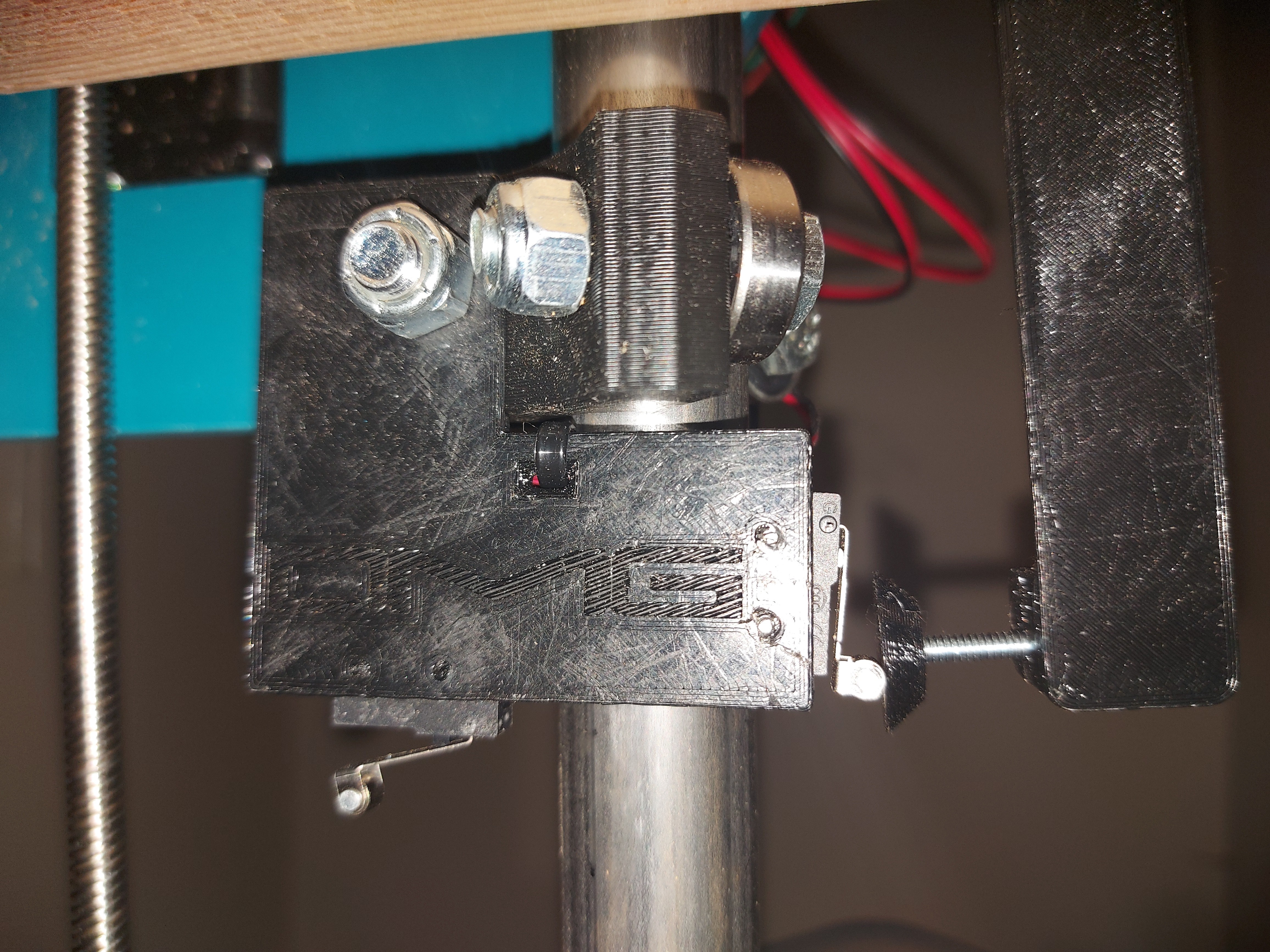
The piece is held with just the one bolt, but is molded to the bearing holder so that it can’t rotate once tightened. It shouldn’t be under much stress anyway.
The plunger stop for the Y axis is less than ideal still, so I’ll redo that.
The X stop is pretty simple.
Just a tube plug, triggers off of the printed part on the carriage
Edit:
Endstops.zip (204.6 KB)
This is the current versions of what I’m using. You need 4x the “plunger”, 2x the “Z tube end” and one each of the other files. The bump stops and the “switch holder” files have both sides. The bump stops are meant to fit right under the Y belt holders, but you may find that they’re a bit tricky to get lined up. Feel free to change those out for something better!
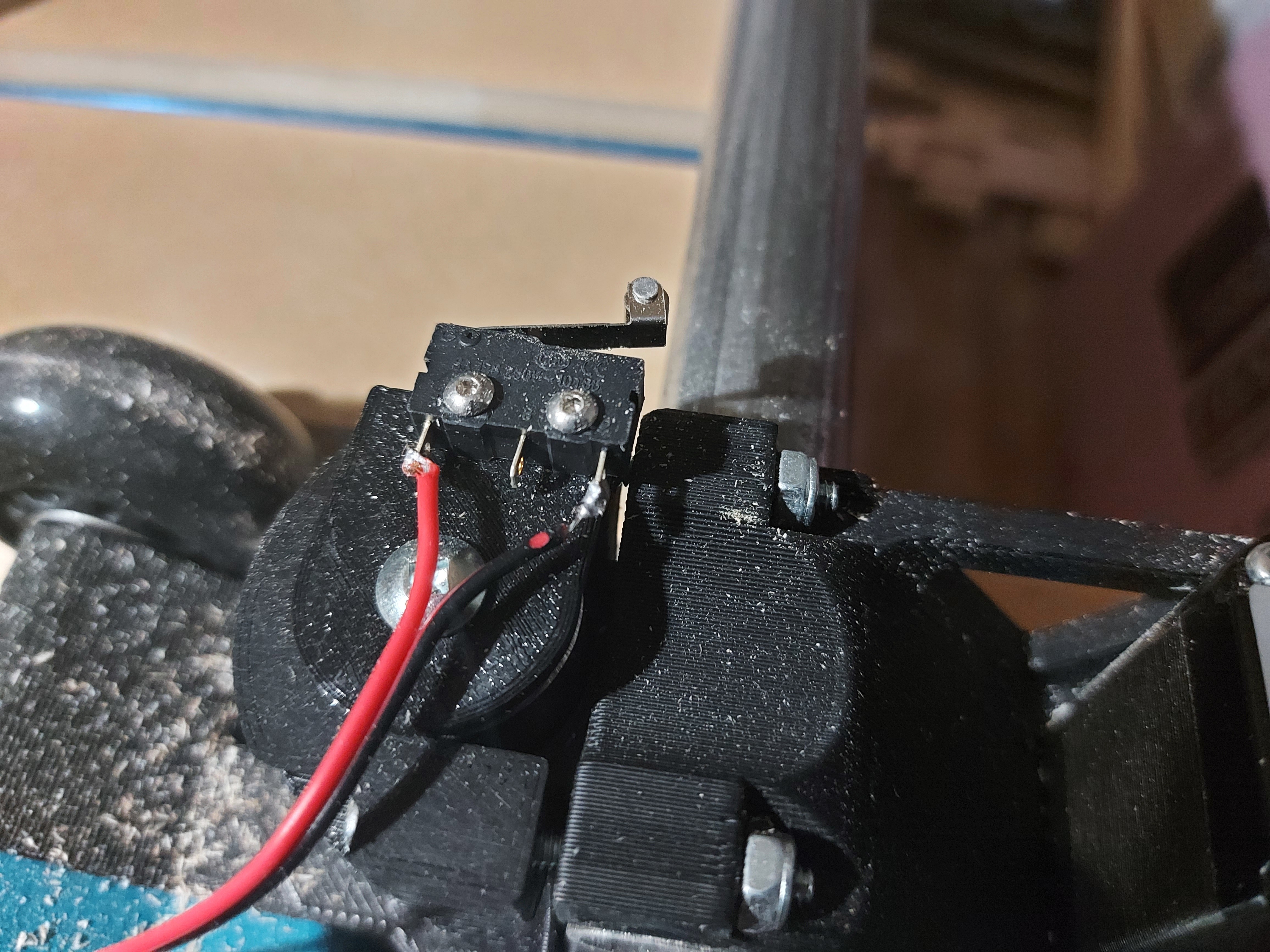
The plungers use #6-32 screws to adjust their position to fine-tube the squaring. I found it easier than adjusting the firmware, and I’d preffer the home position to actually be square, rather than adjust. Probably not critical, but this gives some pretty fine control.
The tube plugs (for X and Z axes) use #8 wood (or sheet metal) screws. I used 3/4" ones. Longer should be fine. The plug tries to expand inside the tube and locks it into place
The switches are held in with M2X10 screws, just threaded into the plastic.