Losing my marbles... Well, not really

Making some stuff real again.

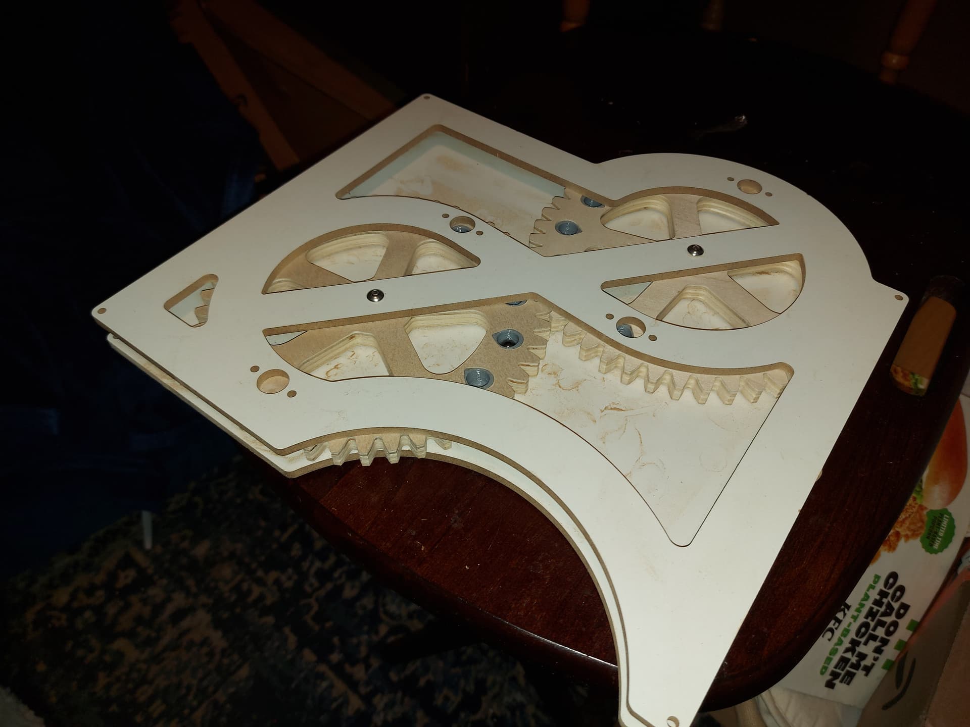
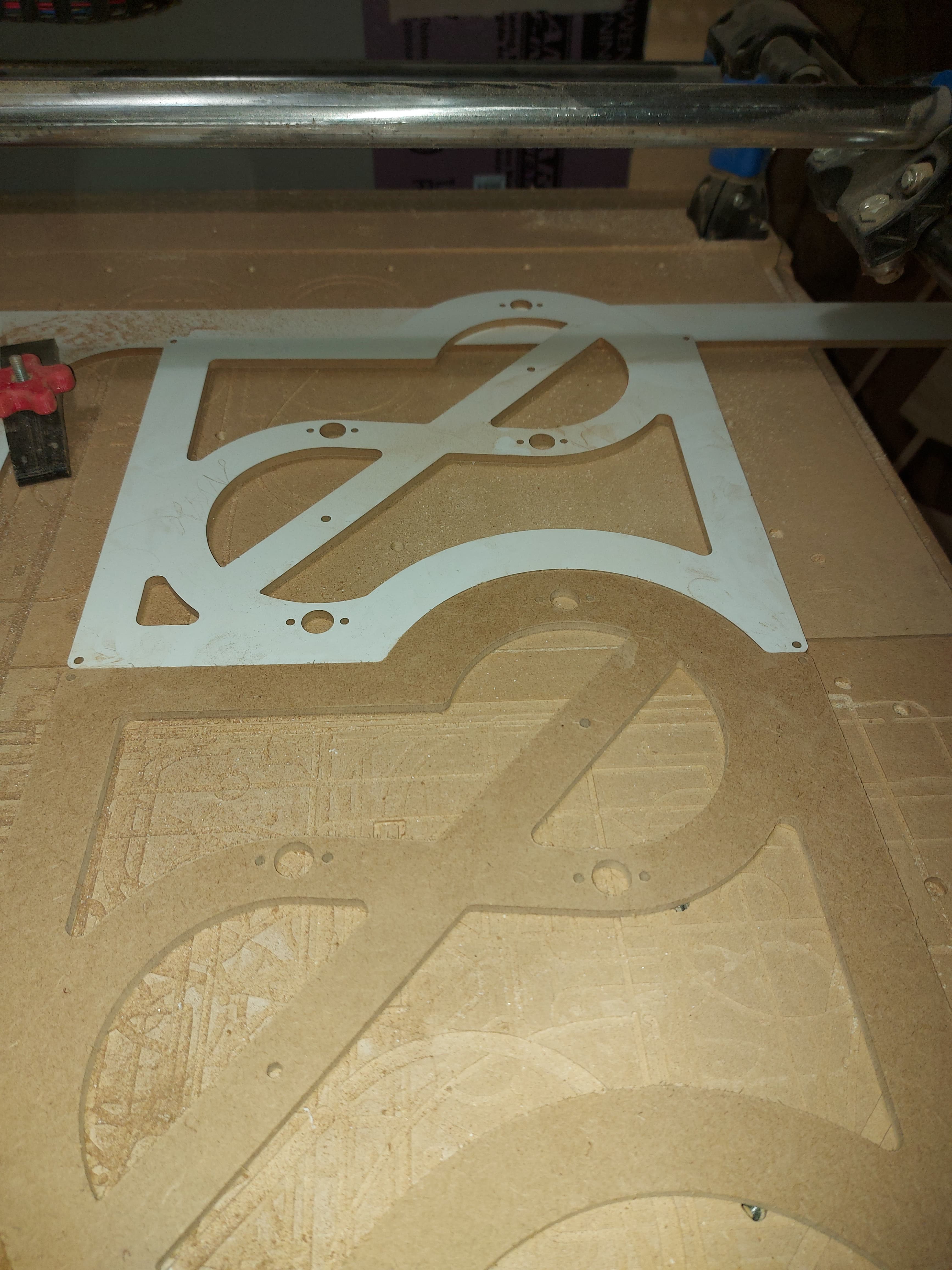
Okay, so I carved out the frames from 1/4" melamine/MDF, and an extra front frame from some 1/4" MDF left over from my Repeat build. I missed the corner by about a half inch or so, or else I could have used it.


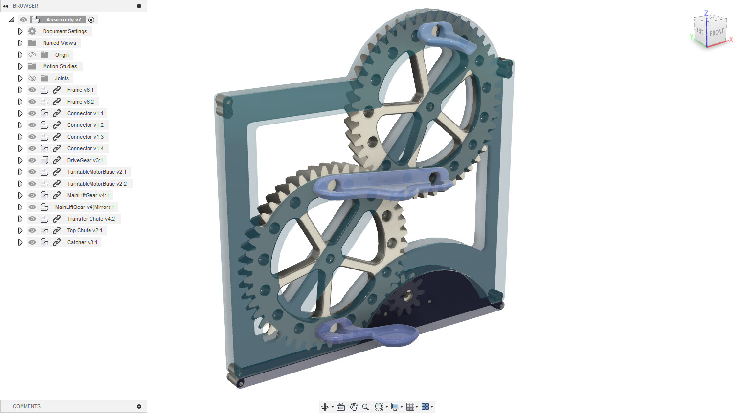
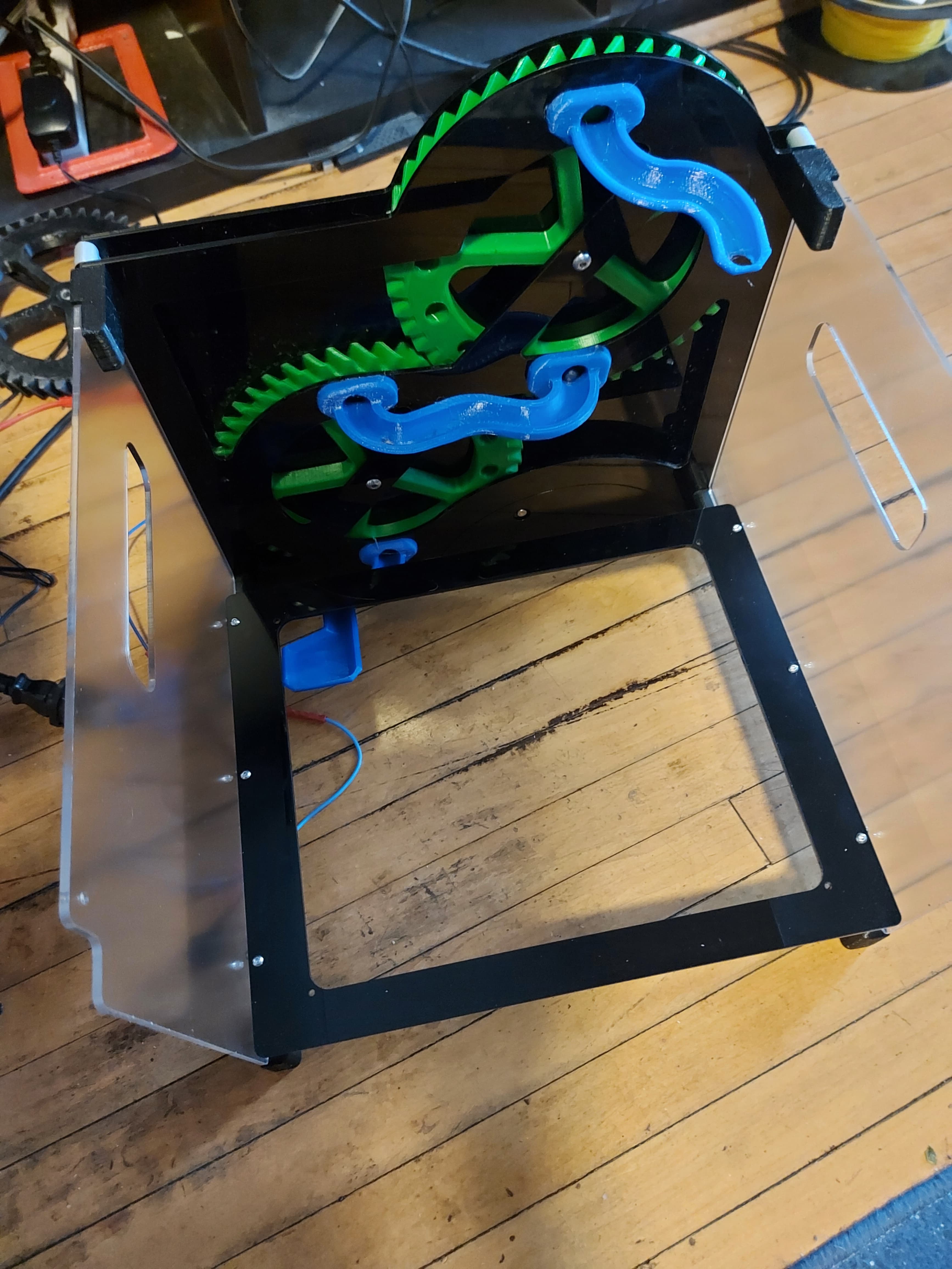
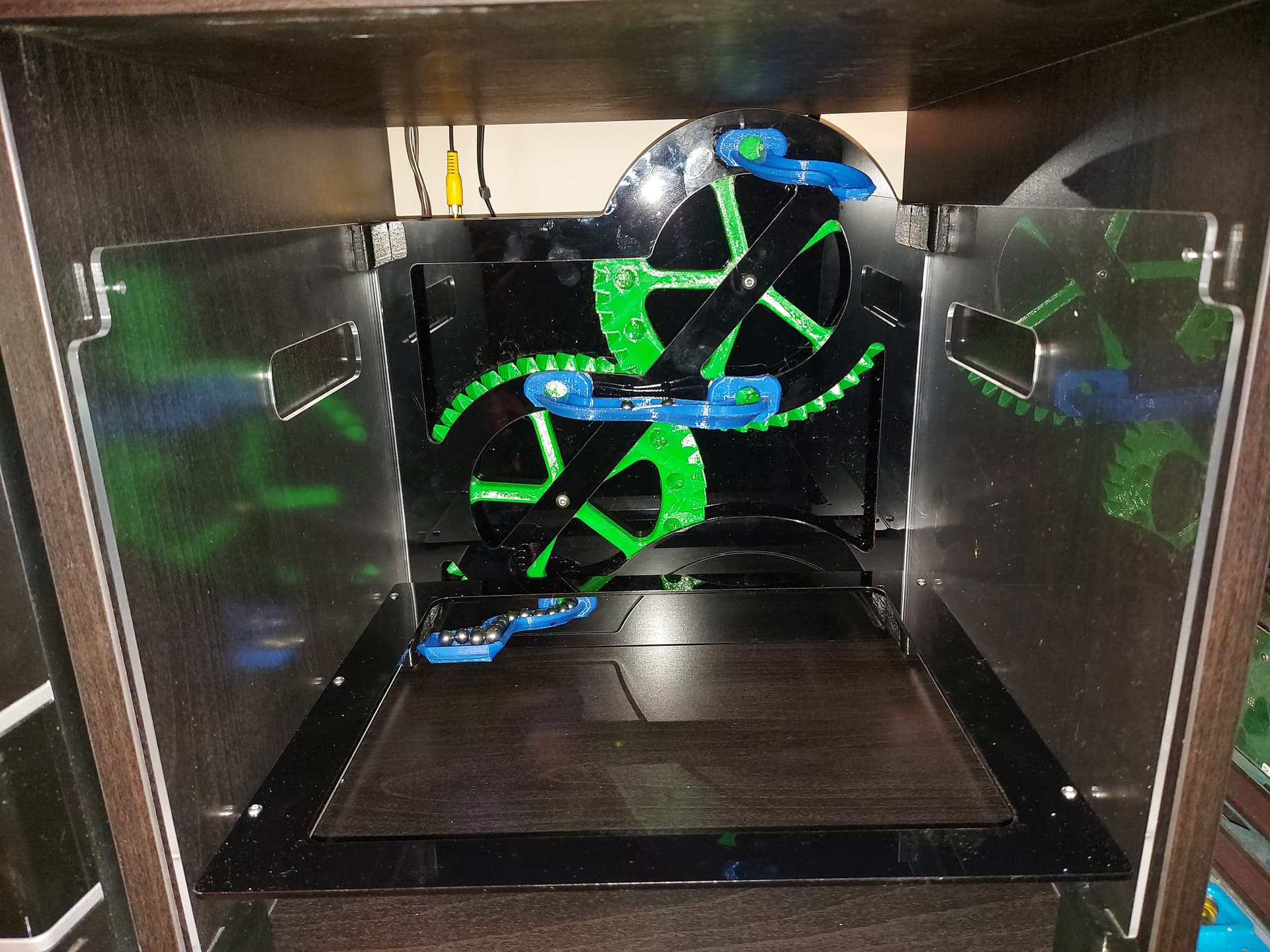
Anyway, as proof of concept for how the frames will stack, it works well enough. With the marble transfer chute printed mirror imaged, that will manage the uptake. I’ll need to design an intermediary chute for the downward path… uses the modules exit directly below the entrances… Hmmm…

I carved one main gear from plywood, stuff didn’t fit. Minor adjustment, 3D printed one… didn’t fit. This time I carved it from foam…

But of course…

Shoulda done that first. The foam is 13mm, so a bit thicker than the 12mm that I designed for, so I had to finish cutting it out with an exacto knife, but this side is all milled, so is a good representation of what the Gcode will do with the real material. Or if I 3D print one based off of the revised file.

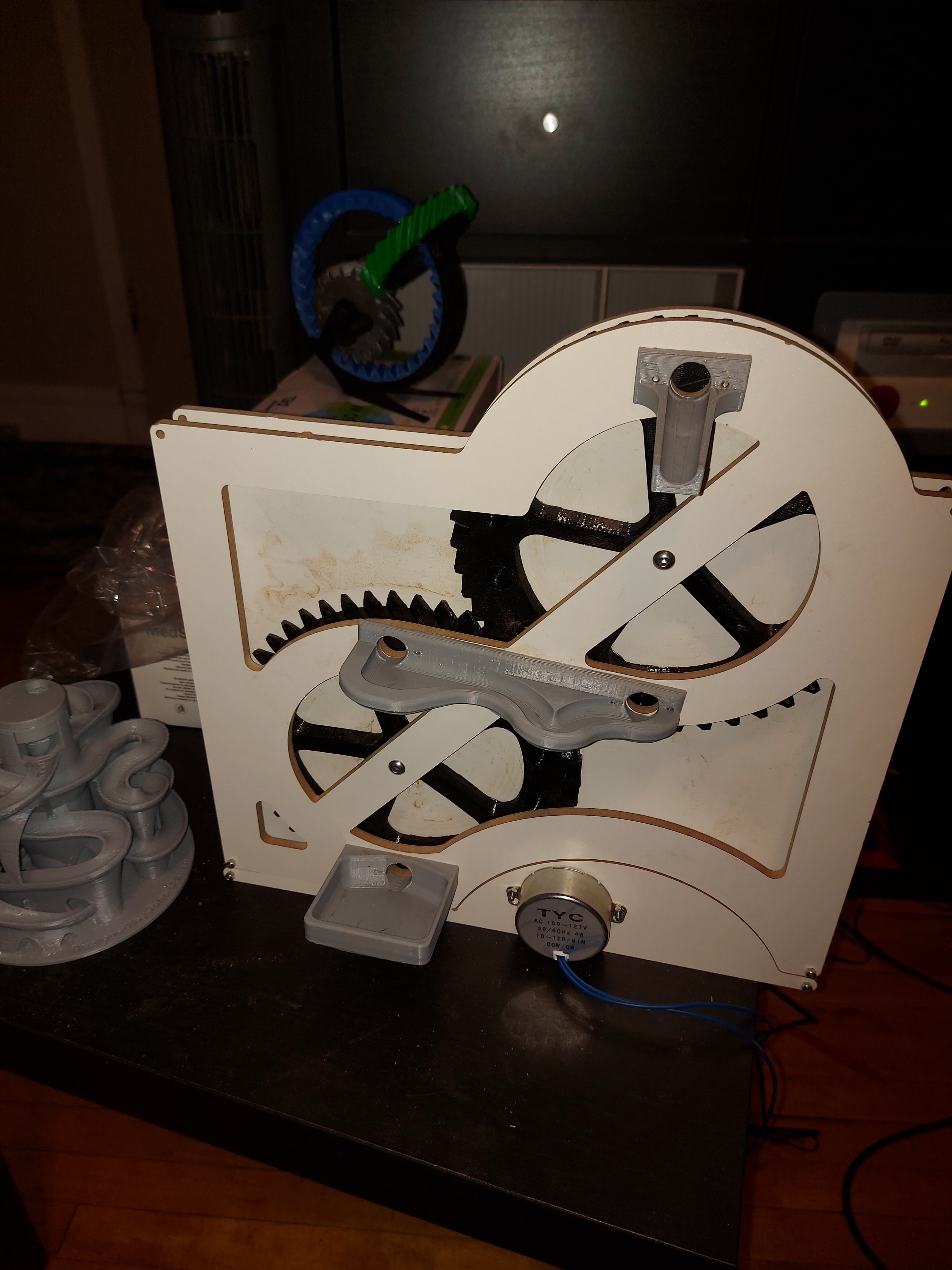
The wheels are set up for some bearings I had lying around, sure hope I can get more. Well they are the ones that the POM wheels are based around. 10mm OD, 5mm ID, 4mm thick, so shouldn’t be a problem to get some somehow. I’ll need a spacer for the center, and washers for the ends to keep stuff from rubbing.

Also printed the little connector pieces for stacking and installing the power base. I suppose I could make an integrated unit that always has to be on the bottom. I’ve been working on this as if I mean to put them into production or something… odd that I’d design that way for something I’m making to amuse myself. Maybe I’ll put some at the local maker’s market, see if I can at least cover material costs…

2 Likes


More real stuff.

Cut the 2 main gears, and fitted the 30 marble socket prints into them, tested that the marbles fall in and out like I want, and the bearings fit in nicely with their spacer.

The 5mm screws are a tad short, so that’s pretty tight right now. No room to fit the transfer chute.

I’ve redesigned the drop chute to move it out a little and drop straight down, I will do something similar with the catch area too.

6 Likes

I was delayed in finding this, but glad I did. Every tinker needs some kind of rube goldberg display in the house, and I can imagine this thing growing in to a thing of beauty, all stained and lacquered up like funiture with mood lighting etc. The modular aspect goes perfectly with it… allows tinkers to make something their own… maybe even design custom modules to set it apart. Mine somehow has to incorporate some sort of rocket launcher.

3 Likes


So this is my first assembly type project in Fusion360. At this stage, I don’t have anything that I did not have in FreeCAD, though some of the details are different.

For example, in this case, the gears are different. I ran the teeth of the gears at an angle, which means that I can’t mill them from wood anymore, they need to be printed. Since they need to be printed, there wasn’t any point in making the marble socket an insert, so it’s molded straight into the gear itself. This allows the inner holes to be a bit bigger.

I copied the front frame directly, and just used it as a component twice. When I make the real one, I won’t cut out all of the holes in the piece, so that it’s the same as the one that I actually made.

FreeCAD’s measurements are weird with arcs and stuff. The measurement that I had was off by 5mm. (I know where it went wrong now.) I was able to get a good measurement off of this… And it’s 2.5mm too tall for the IKEA KALLAX shelving unit with the motor base as drawn. The motor base adds 10mm, and I only had room for 7.5. I will have to re-do that motor base, and the connector parts if I want it to fit.

I had fun with the joints and motion sets, and I can animate the model with the gears all turning. The drive gear is 10T and the lifter gears are 45T, so that’s a 4.5:1 ratio. The turntable motor that I got is 10-12RPM, not very fast. It also isn’t a D shaft like advertised, and it has one more weird feature. When powered on, it goes in a random direction, either clockwise or counterclockwise. I’d guess based on if the AC power (It runs off of 110VAC) is in positive or negative phase when the switch is thrown. I’ve made this si that the motor needs to turn clockwise (Or, when viewed from the front the drive gear needs to turn anticlockwise.) or else the marbles won’t stay in their sockets to be transferred to the top.

Oh, and I managed to model the marble catcher at the bottom in mirror image. I intended for it to go the other direction. :rofl: :joy: :rofl:

Overall, I think that I like the sketcher in FreeCAD better. There are some things that are much easier to do it it, and as a result, there are probably things that I will continue to do in FreeCAD, but maybe import a .STEP file into Fusion360 to finish. The fillet and chamfer tools in Fusion360 are far superior, to the point where there’s little comparison. The sweep tool is awesome, and I’m going to have a lot of fun with it making marble runs, I’m sure.

Well, next is the proof of concept. Time to start printing parts. I am confident that the frame pieces are copied over as-is. I need to make a new motor base, which I can draft up as the parts are printing.

edit: I forgot to reverse the catcher, so I’m printing it as shown… Actually, I don’t think that’s so bad…

3 Likes

So… Ya win some, ya lose some.

The transfer chute works, but there’s a bit of a pinch point in one of the curves. I think I’ve figured out a better way to do this, so I can improve on the overall performance of the part. I think I can make a nicer looking part that takes less time to print, too.

The catch piece is a complete fail. There’s a pinch point that the marble cannot get through. Well, I’m not heartbroken to completely redesign this anyway, since I did it in mirror image. The new one will look kind of similar.

The feed chute at the top works well, but I think I’ll change it up anyhow. I wanted something a little more controlled for an X/Y plane drop of the marble.

The drive gear fir on the motor perfectly. The shaft has a 3mm hole through it for a pin, which will fit into a slot in the gear. Plenty of torque. I like this solution, but I’ll probably look for a slightly different motor in the end. This motor is AC, and I think I’ll keep looking for a DC equivalent.

3 Likes


More real stuff…

Changed to the printed gears. They’re nice but apparently I didn’t get quite enough slope on them, and sometimes they don’t spit out the marbles.with enough force. I’ll make the pitch a bit steeper for the next print.

Added the motor base. It’s a little weak, one of the frame pieces broke while I was mounting the motor. I thought that might be a possibility, but still a bit disappointed. Wired up to motor for testing, the mechanism is fine, just the marbles are inconsistent enough to end up all over the floor. The motor is rated 10-12 RPM. The drive gear is 10 tooth and the lift gears are 45. That gives about 2.5 RPM. Each revolution of the lift gears is 15 marbles, so it’s a bit under 2 seconds between them at full bore. That seems to be a good pace. Plenty fast enough when it’s spitting them onto the floor! :rofl:

This is the old plastic bits on the front, so it needs some updating. The frame is thicker than I hope to settle on, too. This is 1/4" and I’d like to use 1/8" or 3mm, depending. The thinner material will need less oomph to insert or clear the wheels.

I was laughing like a maniac testing this out, but too busy chasing marbles around the floor to take video. I could have caught them in a bag or something if they were coming out in the right place, I suppose, bit sometimes they went too far and fell out of the frame. I should redesign that anyway…

Two steps forward, one step back. So long as the project is entertaining, I’ll keep going.

4 Likes

And now that I’ve got the proof of concept done, it’s time to get the acrylic stuff in place…

The sides are transparent frosted, the back and bottom are black both 3mm as designed. It tends to leave 1 marble at the bottom chute, and maybe 3 at the transfer chute. Once dropped from the tip, it spits out reliably. I may need to redo that transfer chute to get a little more aggressive with the feed.

… now to do the cool stuff that I wanted the lifter for…

2 Likes


And here it is in its Ikea Kallax home.

This is the size that it was designed for, though of course it no longer fits if you stack another on top.

I think what Im going to do is epoxy some neodymnium magnets to the back where the marbles feed into the gears to help feed them. Easier than redesigning the chutes, and even if I do redesign them later, it won’t do any harm.

… and now I’ve got a setup to turn on and off electromagnets baded on a driven gear running through my head as a part of the marble run… or maybe I can use marbles as switches by having them run over contact sets…

6 Likes

I am completely bemused about where you get the time.
Never retire - you won’t get anything done at all. My printer is fully engaged 12hours a day and I have weeks of projects backing up (no no no, I’m not getting another one!)

2 Likes

Can’t wait to see it completed now…

2 Likes

Sufficient time has passed so that it’s not impolite to enquire about progress!!!

1 Like

LOL!

Honestly, I haven’t made much progress. It’s been sharing its Kallax cubbie with various printer bits. I have a handful of components of marble runs, but nothing really complete.

Another victim of my ADHD brain…

2 Likes