Curious if anyone has advice on how to design “Spring” dimensions for intended deflection force and distance? Wondering if there’s a simple formula or online calculator for this scenario, or if I should learn to use something like CalculiX, Elmer FEM, FEniCS finite element analysis software ( FEM - Finite Element Method )?
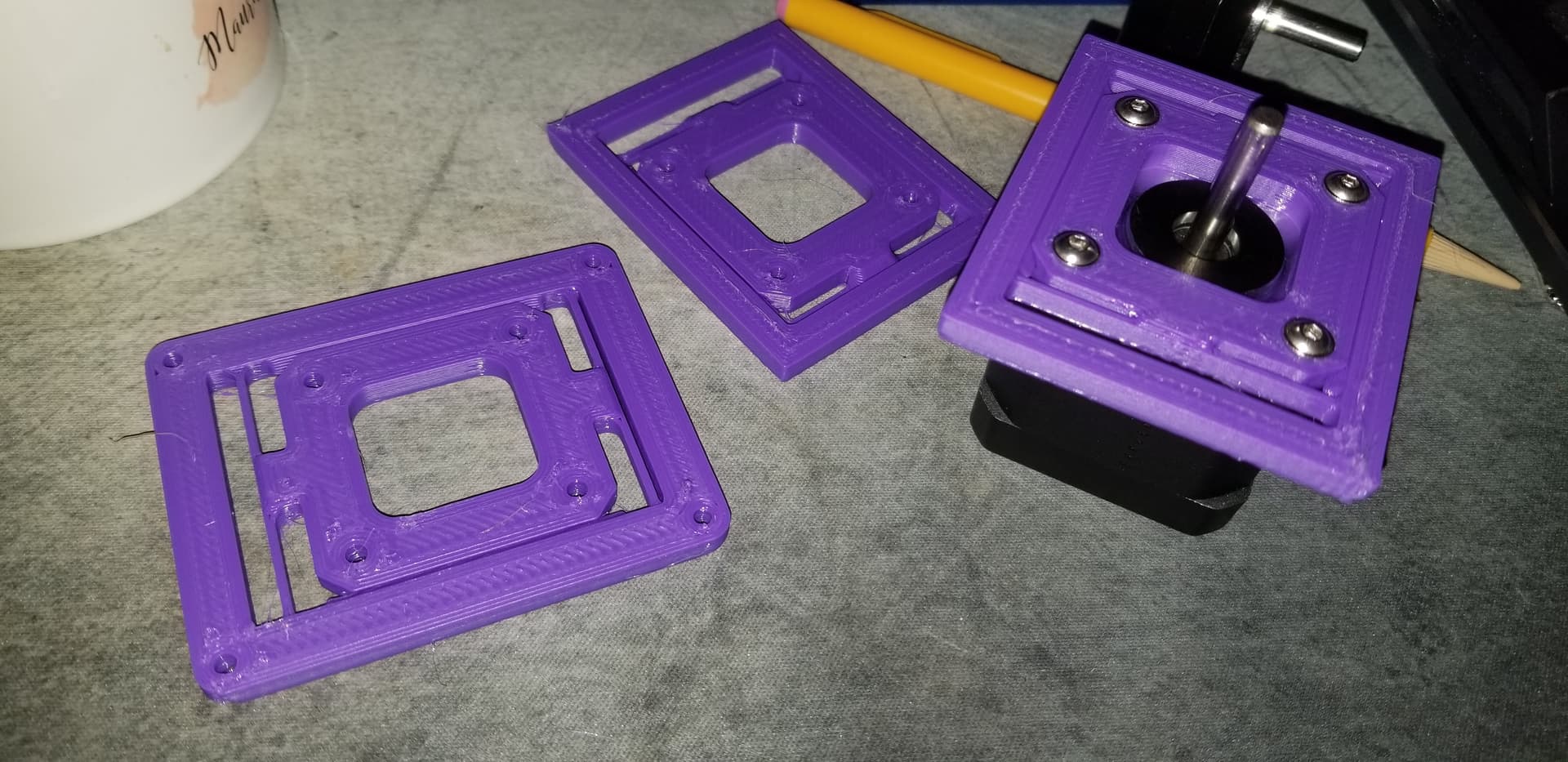
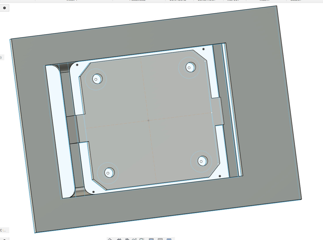
Am trying to mount a Stepper motor onto a plate with built in linear spring compliant mechanism to give it some limited motion (max 5mm left), want initial resistive force ~30N at 0mm deflection, then increase resistive force from there (non linear increase is good). PETG 2.1GPa. Here’s a basic example to help visualize what I’m doing, it’s incomplete and missing rotation constraints…
Am NOT trying to design a Constant-Force Mechanism like this cool contraption https://www.printables.com/model/583491-constant-force-mechanism…

Rather, I’m trying to make “regular linear springs which yield an increased force with greater displacements”.
Think I’m trying to do something basic, despite all the cool things that can be done with compliant mechanisms, e.g. see BYU CMR’s research, or BYU CMR’s Compliant Mechanism models on Printables.
Guessing there’s an online calculator for “Linear spring compliant mechanism” that I’ll stumble onto it as soon as I send this out… Cheers!
EDIT: fwiw - am kicking off test print(s) in parallel while I try to learn enough Freedom and constraint topologies (FACT), FEM theory on things like /software to get this done. Using FEM is probably overkill for this scenario, but would be nice to learn and use before making more time/material costly Alu iteration(s) later on.
EDIT: meh, this is good enough…