I tried to wire up my limit switches on my V13DP V4 and have the following questions.
Does the SKR Pro 1.2 board require 3 wires for the limit switches or can I use 2?
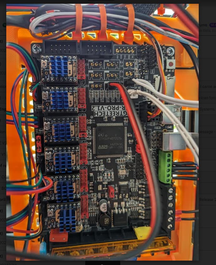
I tried to use just the C and NO wires (black and red) however when i plug them into my board i loose the 3v, 5v, and 12V led’s when powered up by my power supply. the 5v led seems to flicker lightly? Then I hooked up to USB power to limit risk and same thing happens…
Would this be caused by not using the third wire, or is it a short in my cable? Or am I using the wrong pins on the board?
I could just play around with pins, but worried about damaging the board.
Great catch, I slid the connector over one pin (uses the middle and right pin on the SKR board and the switches seem to be functioning normal… i.e triggering the stepper indicator light on the board.
When i tried the home function on the touchscreen, the head unit moves properly from right to left and front to back triggering the switches and stopping the head unit, however once the head unit moves back to the center of the print space, marlin is outputting the following error codes.
When home function is used on the touch screen and homing completes the following error codes are…
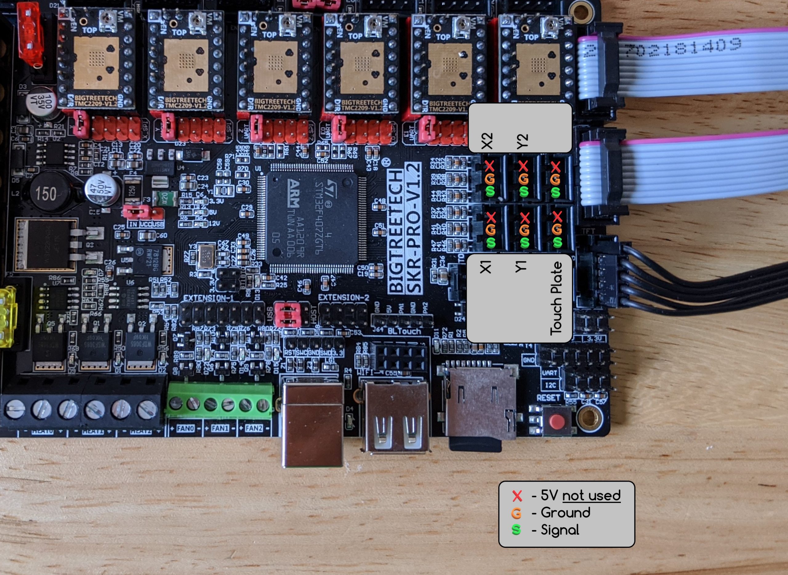
Looks to me like you have connected the + and ground… that will short the 5V power which will shut down the board. You want to use only the signal and ground wores, NOT the +5V
you want to stay away from the pins marked with the red “X” The orange “G” and green “S” are the ones you want to wire to the NC pins of the switch!
Edit: there is one way you can use all three, but it is neither necessary, nor recommended. If you wire the +5V pin to the NO terminal on the switch (center) then the S pin to the Common terminal and G to the NC pin, it will work. (But if you get the common and NC terminal mixed up, the board will short the 5V power when the switch is touched, so… just don’t.)
I’ll second that: don’t use the 5V pin… I fried the regulator on my board by having the end stop connected to power and ground. Instant short of power to ground. That is bad.
You want the signal goes to ground when the endstop is not in use and it disconnects when the enstop is pressed. No voltage is needed for this.