Does anyone know if it’s possible to achieve a 0.2 mm level of precision on a 370x370 mm surface with the MPCNC while cutting/surfacing aluminum? If so, any tips?
I would imagine that depends a lot on the quality of your build (rigidity, squareness, etc.), and the thickness of your stock, along with several other factors (size of end mill, feeds and speeds, amount of stickout/deflection, proper use of finishing pass, etc.), Others have achieved that accuracy/precision with the Lowrider, not sure about the MPCNC
Trochoidal milling and use of air/mist system can help with aluminum milling.
1 Like
You definitely can. ![]()
I’ve heard you need tools that measure with 10x the accuracy of the tolerance you’re trying to achieve. Are there any measuring devices that have 0.002mm of accuracy and aren’t crazy expensive?
I think you might mean ± 0.02mm, then? That’s well within the accuracy range of a decent set of calipers. My Mitutoyo digital calipers came with certification to ± 0.001" /0.025. I’ve checked all my cheap ones vs them with a couple of measurements on gauge blocks and they’re all within a count.
I’ve seen the 10% rule of thumb before for measurements and I think that’s just so you’re not throwing away a ton of your tolerance band in the measurement. If you’re aiming for 20mm ±0.2mm and you can only measure to ±0.1mm then your actual recorded measurement needs to be between 19.9mm and 20.1mm to know that your actual part is in the range of 19.8mm to 20.2mm… In general it’s a lot cheaper to measure things more accurately than it is to make things more accurately. It doesn’t mean you absolutely need that, though, if it’s a one-off thing then carefully getting to 19.9mm to 20.1mm might be good enough.
There are also a ton of methods where you don’t need an actual numeric measurement, such as using gauge blocks with comparators, shims, etc. If you’re willing to get creative you can make some pretty hilarious indirect measurements…
But fundamentally, as long as you’re willing to be careful, I’d say you could easily work to ±0.2mm with a cheap set of digital calipers. Way below that with even an AliExpress micrometer. In my case I’m lucky enough to have access to good equipment at work that I can use to check my cheap crappy stuff against…
I don’t have any direct experience with this but I think it’ll come down to what you’re trying to do.
If you’re trying to get something straight off the machine first time with everything within that tolerance then I’d be a bit skeptical.
If you’re trying to get some specific dimensions dialed in so you can do it repeatably then I’d say that should be relatively easy, although it might take a couple of rounds of measuring and adjusting accordingly.
One issue is that you can make light cuts to sneak up on dimensions but the thickness of cut you can make is a product of the sharpness of the tool and the rigidity of the machine. You can’t make an infinitely light cut without the tool just rubbing and refusing to cut. Another issue is that once you get to that kind of scale you’re in the range of movements being less than a single full step of the steppers so the actual position moved can start to become non-linear. A commanded movement of 0.1mm won’t necessarily be exactly 0.1mm. I don’t think that’ll be a huge issue, though.
I would personally say ±0.5mm is likely to be easy, beyond that will take a bit of futzing with it but ±0.2mm should be achievable.
That’s all speaking relatively within the same job, of course. Having those measurements come out accurate compared to other existing features will have a bunch of other requirements such as using good technique when probing/aligning the work.
1 Like
Yes, that was my mistake. 0.02 would be correct and a lot easier/cheaper to measure than what I stated.
I’m exceptionally uneducated when it comes to metrology, but it does tickle my tool fancy. This is all very good stuff to read BTW.
1 Like
When you see the inlay projects that have been posted I would say yes 0.2mm and much less is clearly very achievable.
Despite what you might read from others who say say 0.5mm is the best it can do - there is ample evidence to the contrary.
2 Likes
I am currently “exercising” 3D-miling but on wood.
My parts are round about 1m (1000mm) long and I need to realize it in different steps because my working bed supports only 520 mm.
So I have to realize it in 4 steps, 2 on each side moving the object etc.
Even here I get a precision of 0.1 - 0.2 mm in moving and turning the object a couple of times.
With aluminium - even AW7075 - I get 0.1mm precision but of course you need to reduce speed.

5 Likes
Your real issue with be temperature. If you’re chasing zeros. It’s definitely possible but it will take a long time.
Is your shop temp controlled ?
How long will you part be machined and cooled to be measured ?
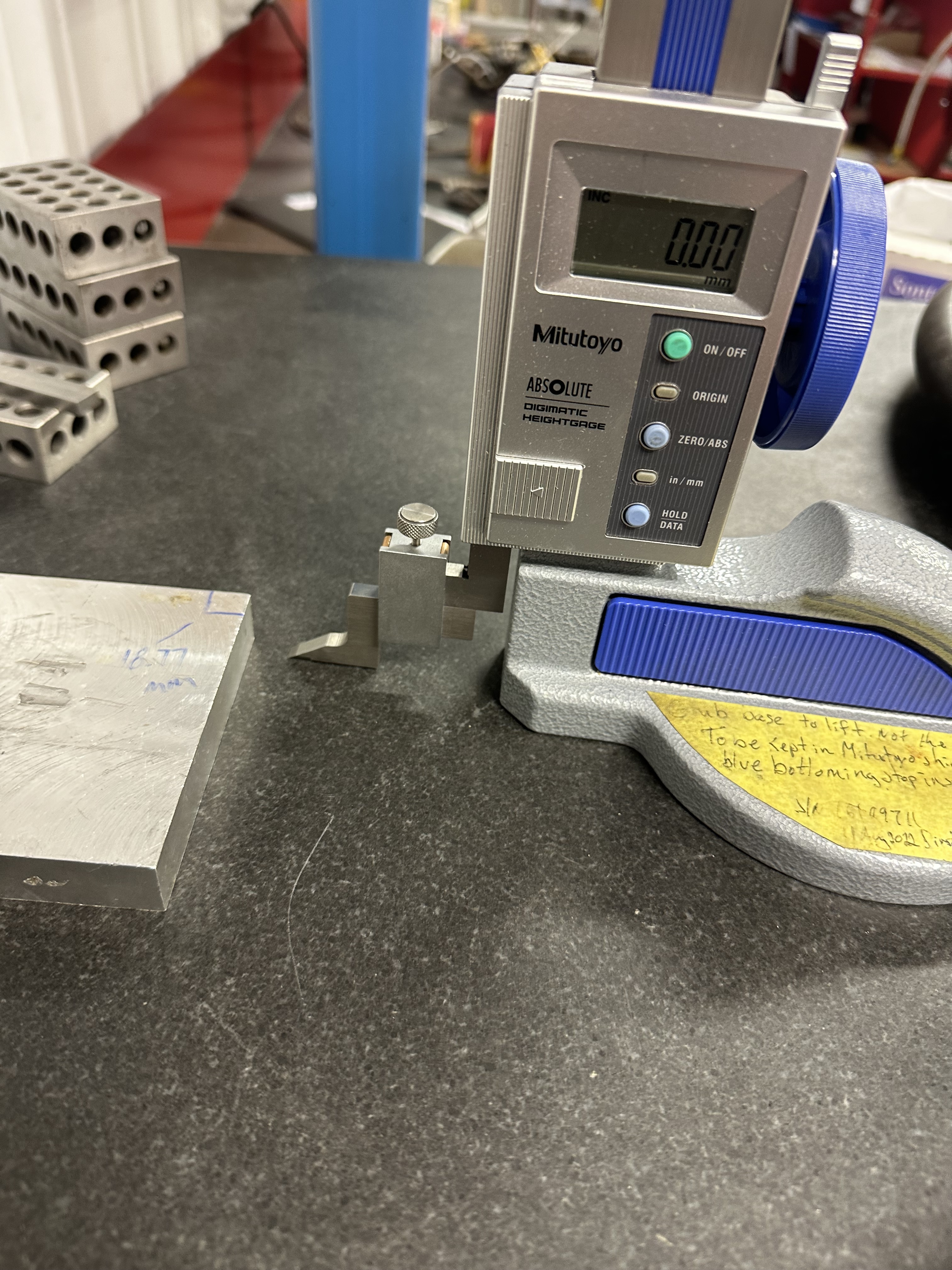
Here is a quick example
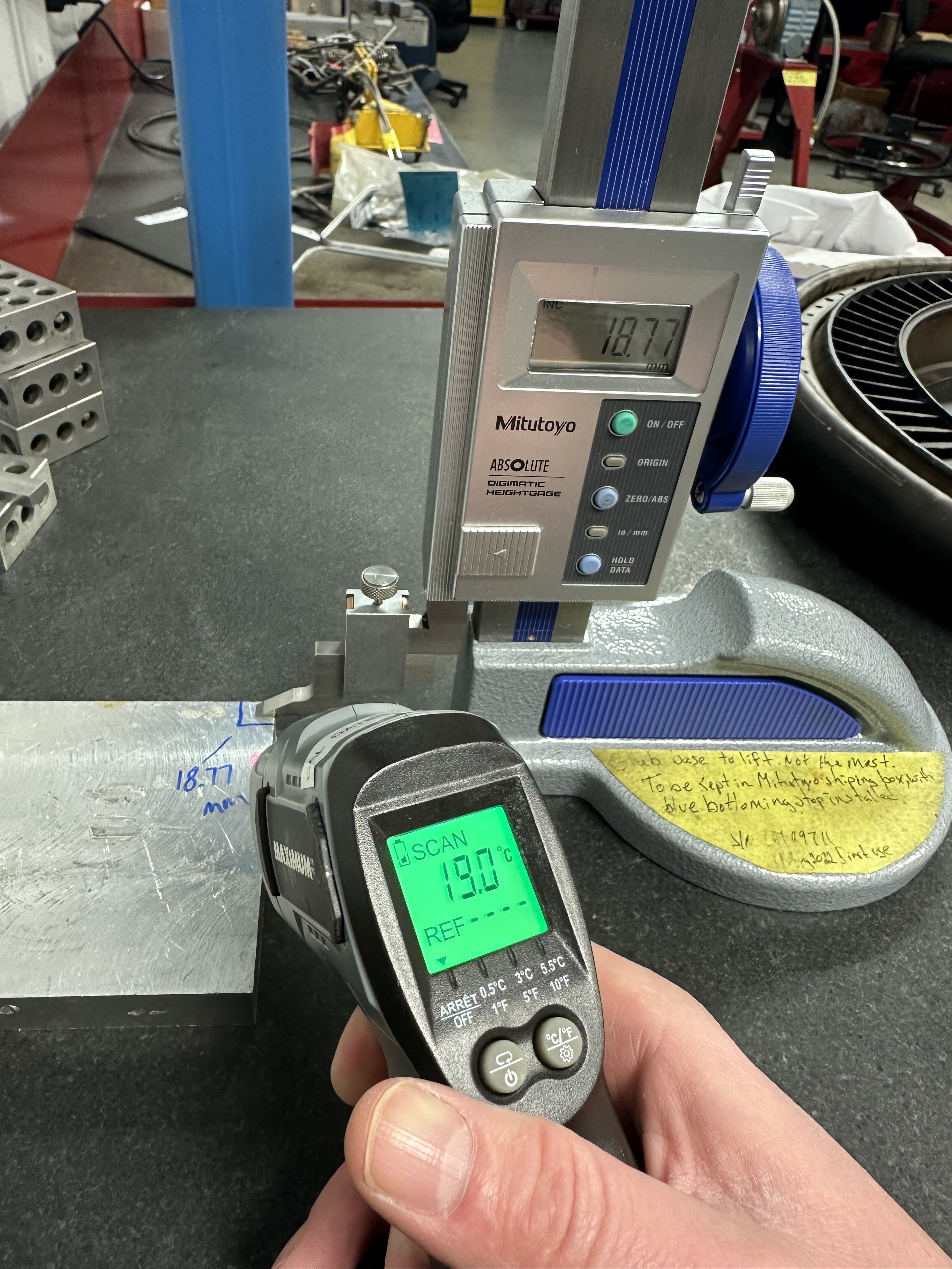
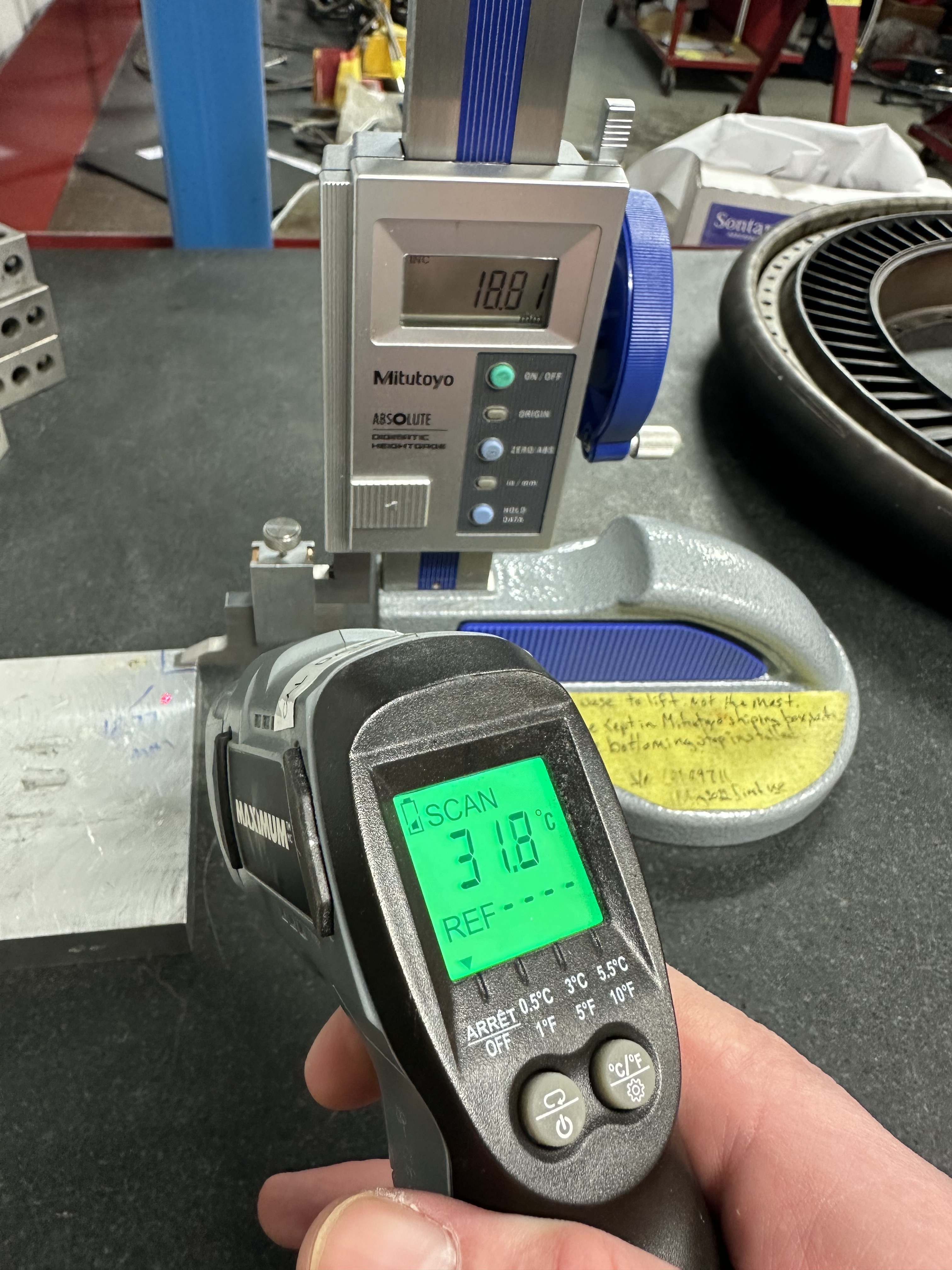
I work with a lot of thoriated magnesium and ohh boy does that love to expand with heat. In fact the engine I build grows quite a bit when it’s at full power.
That’s just a random chunk of 6061
1 Like