Learning Estlcam with a Snowblower Part

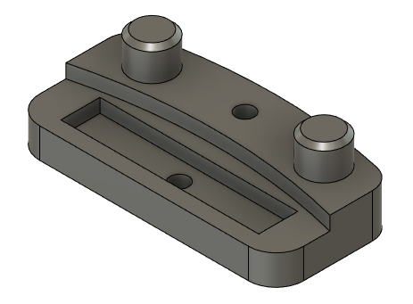
I’m just trying to cut this out on my LR3 as a learning experience. It’s a replacement part for my snowblower that I created a model for and 3D printed a few years ago. If I needed another one, I would just 3D print it again, but I think this might help me wrap my head around Estlcam.

(Didn’t plan on making a post this long but it helped me think through it as I went.)
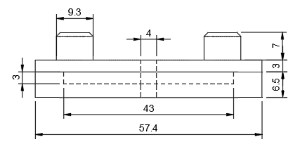
image

Depths:
image

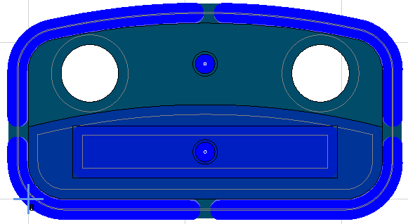
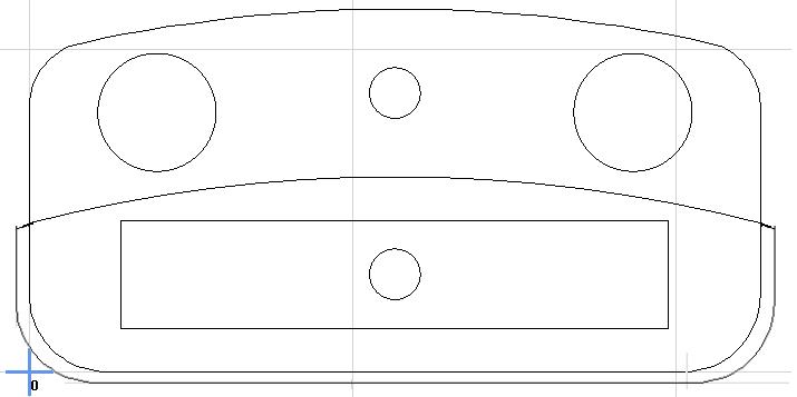
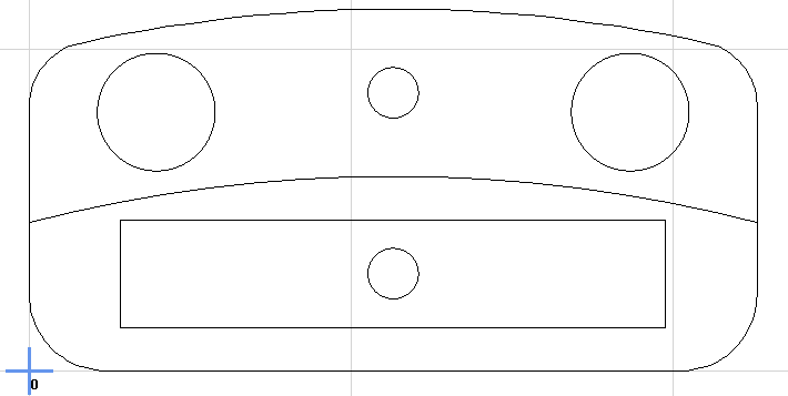
Loaded the DXF into Estlcam.

For simplicity’s sake, I’m going to assume that I’m starting with material that is already the correct finished height. Or, if the bottom is thicker, that doesn’t affect functionality.

Thinking through it, the total height is only 16.5mm, so that’s feasible to cut with a normal endmill but total height is a limiting factor.

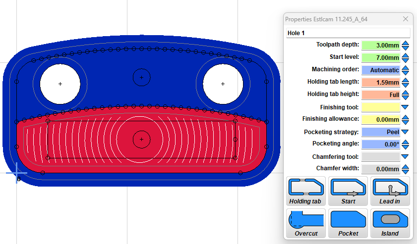
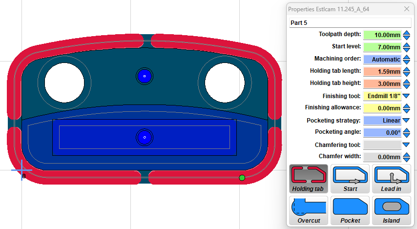
Those two top posts are islands? Not worried about the chamfer for now. I could bring the whole thing down to the level at the bottom of the posts (7mm).

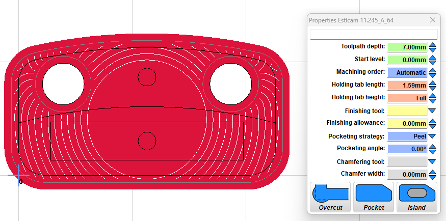
From there, I think I want to take it down to the second level on that bottom half, so I’m creating a hole with a pocket? Estlcam didn’t like automatically selecting that shape so managed to figure out manual shape detection with the built in instructions.
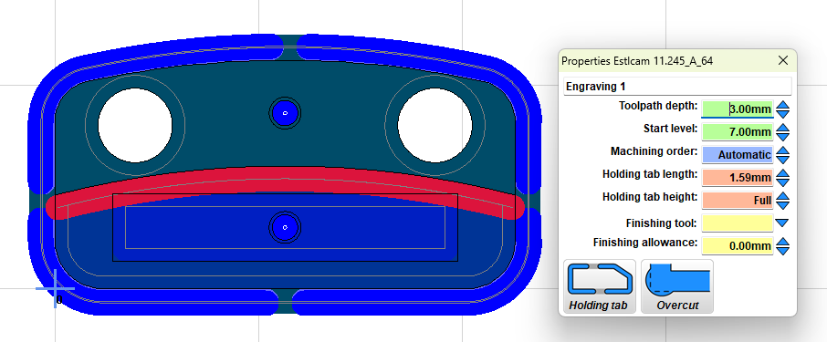
Go down 3mm starting at 7mm.

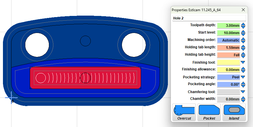
Then the bottom rectangle. 3mm deep starting at 10mm.

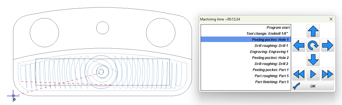
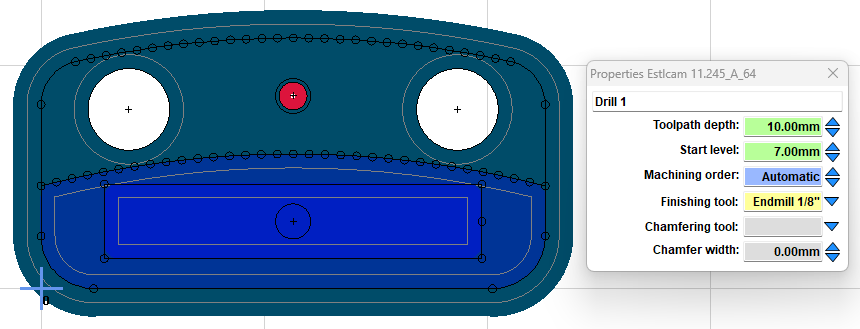
Then back to the holes. Top hole starts 7mm down, make it go 10mm to give me an extra 0.5mm.

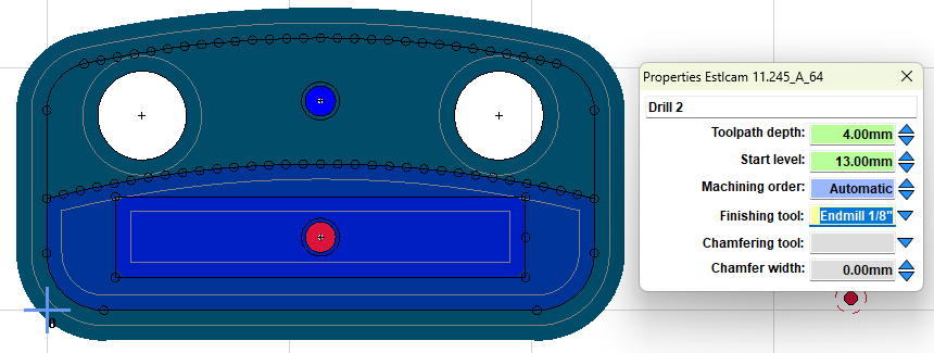
Bottom hole starts 13mm down, use a depth of 4mm for an extra 0.5mm.

Then finish cutting the part all the way down with tabs this time. Already took it down 7mm with the first pass.

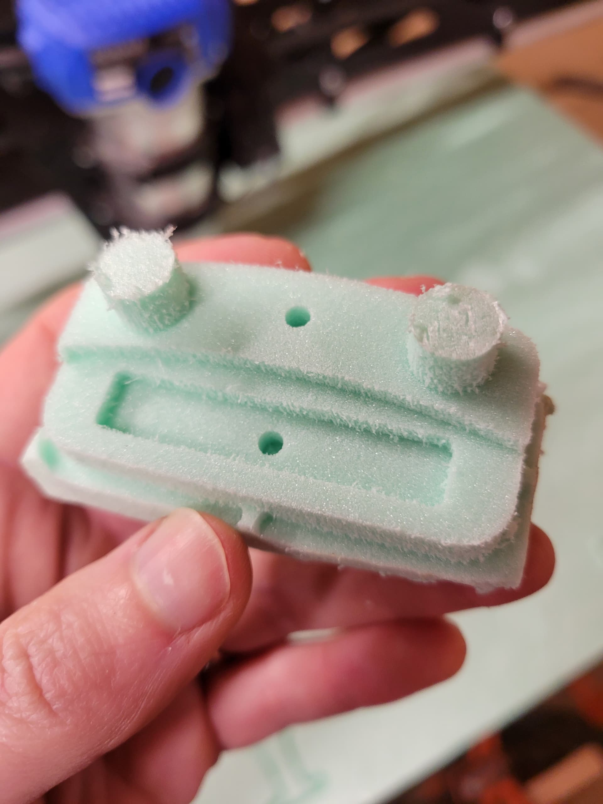
I’ll give this a shot in foam tomorrow. Does this sounds reasonable?

It’s a bit hard to navigate all this after the fact. Any suggestions?
image

2 Likes

Looks right! Neat. Adding the chamfer is pretty easy now, too.

The corner on the innermost rectangle is fine, but the ones on the side by the tabs need to be gone. At first I overcut the corners but that’s not really what I wanted. So, I engraved below the curved line at the corresponding depths.


Automatic machining order would have gotten me into trouble very quickly. It wanted to do the lower half first!

Cool.

Foam is much thicker than the part but I knew that.

Should probably get back to a project that takes advantage of my LowRider’s working area but I got what I wanted out of trying this.

5 Likes

Jason, great ‘thinking out load’ description. With the screenshots along the way. This helped me as i thought what i would do and it matched your method. Now i am interested in how that chamfer would be done :thinking:

Thanks again for this post.

1 Like

Glad my stream of consciousness was helpful. I suppose I should try the chamfer. I think I need a 90 degree V bit to put a 45 degree chamfer on it. I only have a 30 degree bit but that should be good enough to figure out how it works.

1 Like

The easiest method is just to engrave on the line with the 90° endmill. If you want to be sure there is no remnant, do a little offset.

2 Likes

Looks good. One thought on that arched pocket is that you could edit the drawing to create a separate arch and perimeter object. The benefits are one click path selection and no missed (corners) or potential leftover/lost bits from cutting to both sides of the line w/ no overlap. If it was a rectangular pocket adding a negative finishing allowance (tool radius) and then Moving the path down by the same amount would work, but doing it with the arched pocket would increase the cut arch radius (+ tool radius).

Setting up all V-bits with a Center (and Tip if its flat or radiused) offset for more efficient ‘away from the tip cutting’ is a good idea, but those settings are only used when adding a Chamfer path using the path properties Chamfer tool and width settings (depth varies w/ tip angle). Doing that with the island pocket would result in both the perimeter and island posts getting chamfered.

As Philipp said, the easiest alternative is to set center-line Engraving paths and cut depths (/widths w/ 90V) for the posts. Another option is center-offset right side Engraving or Part paths:

Cut depth = chamfer depth + center offset, e.g. .75c + 1o = 1.75d (<= tool radius)
Negative Finishing allowance = tool radius - center offset, e.g. 2r - 1o = -1fa

2 Likes

Not sure I want to modify the model for this, but I understand the advantage since I wouldn’t need a second path to get those curves. I did have a super slim leftover when cutting the inner rectangle but it was so thin it practically fell off. I wonder if that means my bit is slightly less than 1/8 inch.

Well, that’s an important detail I didn’t realize.

The thing I appreciate about the lowrider is that it can do both big full sheets yet is also capable of much finer and more detailed work.

1 Like

I finally am able to get back to learning and understanding the different options/setting within Estlcam (v12 now). Phillip, when you say ‘do a little offset’, is there a setting for that or what do you mean by that?

I tried to watch the video linked in the pop-up help, but I think I missed a lot with it being German - I tried to use the ‘transcript’ and have YouTube translate to English, but I don’t think it did a good job. :laughing:

There is a field where you can specify a clearig toolpath. Make it a little bigger and do not select a tool, this will create ann offset for that path. I think 12 has a chamfering option included, I didn’t try it yet though.

Using the Chamfer tool/width options on an existing path is the best/easiest option, doing the same chamfer with a separate right or left of the line Engraving path requires some math. The easiest, but less than ideal (pointy tip cutting) separate path chamfer option is on the line Engraving, just enter the desired depth (which is the same as Chamfer width when a 90 degree V-bit is used). Using a Finishing allowance (offset path) is only an option for R/L of the line Engraving (and Holes/Parts).

Half tool radius alternatives to the pictured Offset method:
Toolpath Depth and negative Finishing allowance (FA) set to half tool radius equals a zero width (90V depth) chamfer. To get a desired chamfer width add it to the half radius negative finishing allowance. The desired chamfer width needs to be a bit less than half the tool radius.

16mm cutting diameter = 4mm half radius
Depth: 4 and FA: -4 = 0 chamfer
Depth: 4 and FA: -6 (4 + 2) = 2 chamfer width (any V-bit angle)
Depth: 4 and FA: -7.9 (4 + 3.9) = 3.9 ~max chamfer (.1 away from top of 90V cutting edge)

Depth + width chamfer = larger max chamfer (1st matches image offset method):
Depth: 5 (4 + 1 half chamfer) and FA: -5 (4 + 1 half chamfer) = 2 chamfer (w/ 90V)
Depth: 7.9 (4 + 3.9) and FA: -7.9 (4 + 3.9) = 7.8 ~max chamfer (.1 away from tip and top of 90V cutting edge)

Thanks Dave. I’ve been reading and re-reading this. It is sinking in, i think, slowly. The ah-ha moment hasn’t come yet but I’m not giving up. I haven’t had the time to test this out on the machine, yet. Maybe tomorrow I’ll play. Thanks again for the explanation.

1 Like