I’ll apologize at the start for being a bit long-winded. I tend to overcomplicate and overexplain things. 
I have no real background in woodworking, electronics, or almost anything else related except for a touch of programming experience and flashing custom ROMs on phones, so building a Lowrider v2 has been an adventure and a steep climb!
I have my LR2 up and running and can successfully draw a picture with a pen strapped to the tool mount. With that out of the way, I moved on to setting up the laser as my fiance wants me to wait on routing.
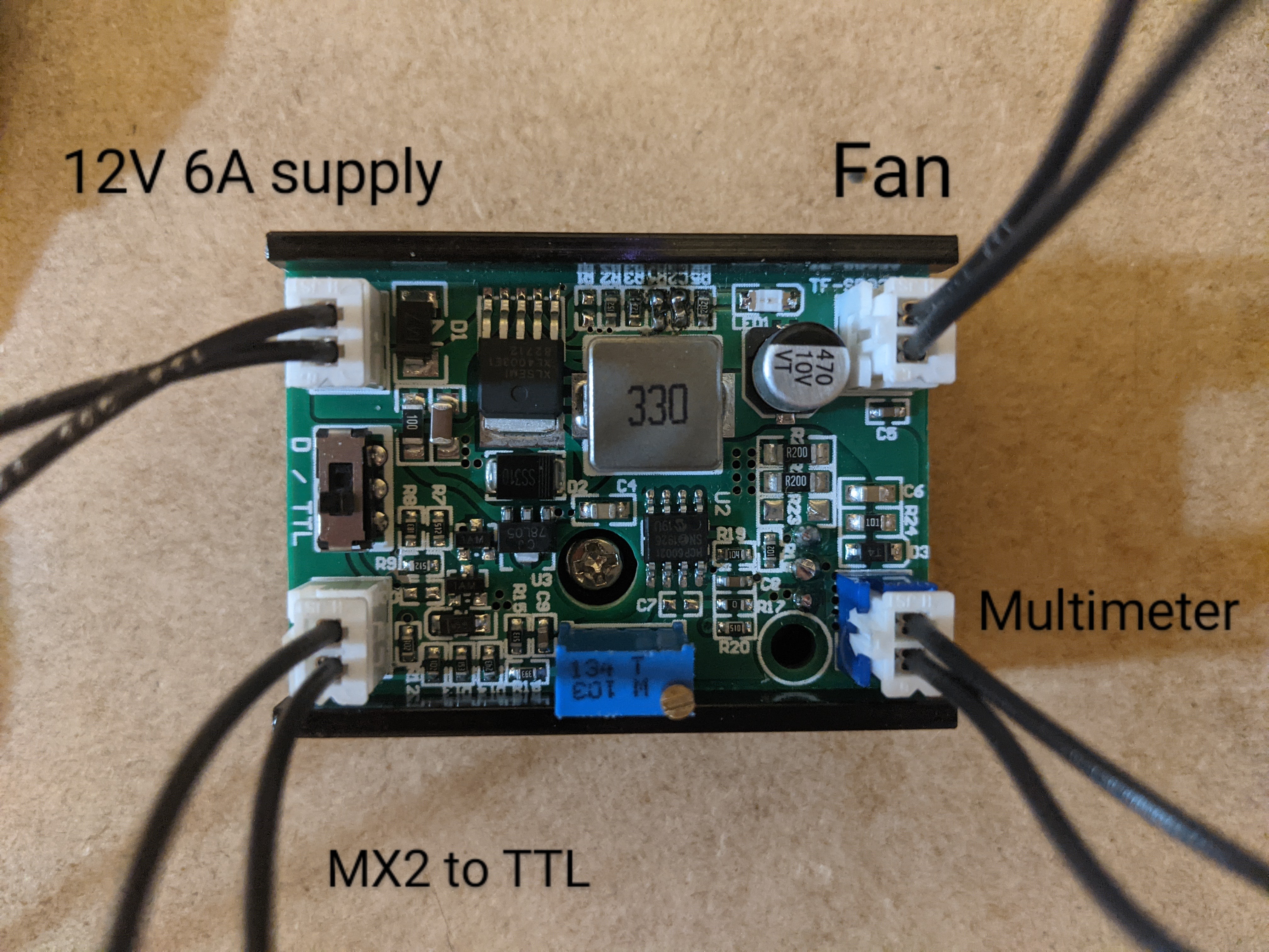
I am using a RAMBO 1.4a board with a laser driver from techhood on eBay (but it looks different from the picture) and am following the instructions from “The 2.8 watt, $100 Laser Upgrade”.
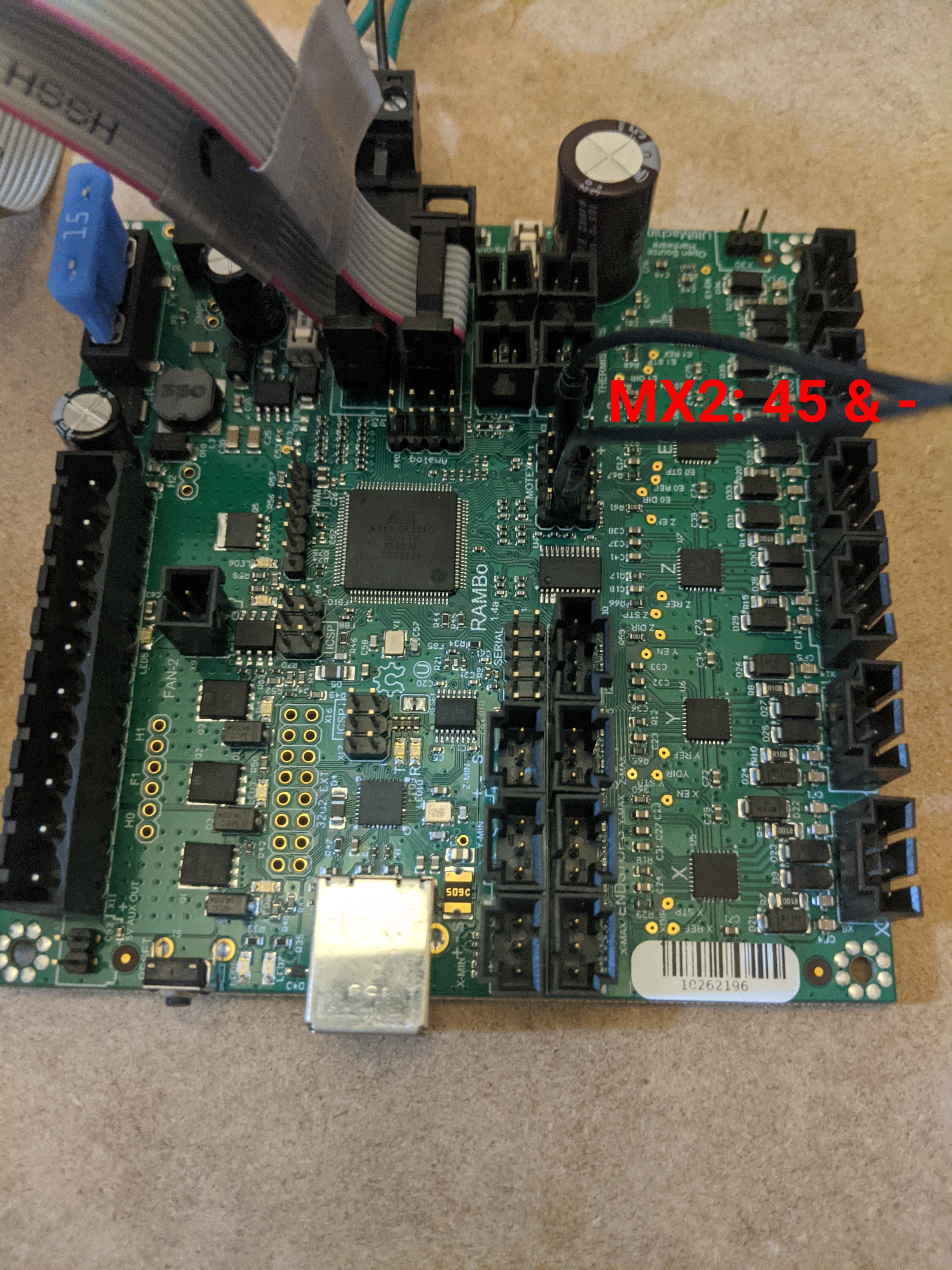
When I test via pin 45 on the RAMBO with the laser set at 255 and 127 power, I get results of 5V & 2.5V respectively. When I connect the driver, however, I’m getting stuck.
The instructions reference two adjustments to be made, one for current and one for voltage. I am only seeing the one for current (but no amount of turning makes the only LED turn off) and the only screw is not actually on the board but underneath it and doesn’t appear to have any effect.
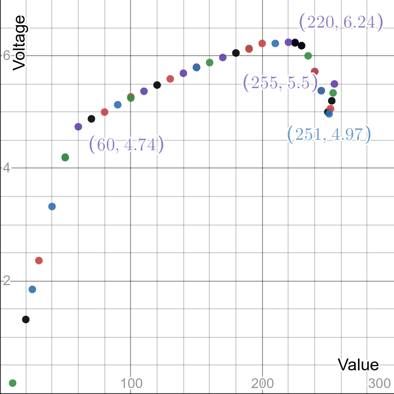
If I adjust the one that the instructions reference for current until I get the voltage at 5.5V, I can then use the RAMBO to adjust things but the voltage doesn’t change as I would expect it to. As I drop the laser power from 255 towards 0, the voltage drops slightly from 5.5V, rises to 6.2V, then drops slowly again as it curves back towards 0V.
I have included some pictures of my temporary set up so that you can get a better idea of what’s going on.
My Rambo board with TTL wires:
The driver:
The voltage outputs I’m getting from the LD pins on the driver for the corresponding laser values: