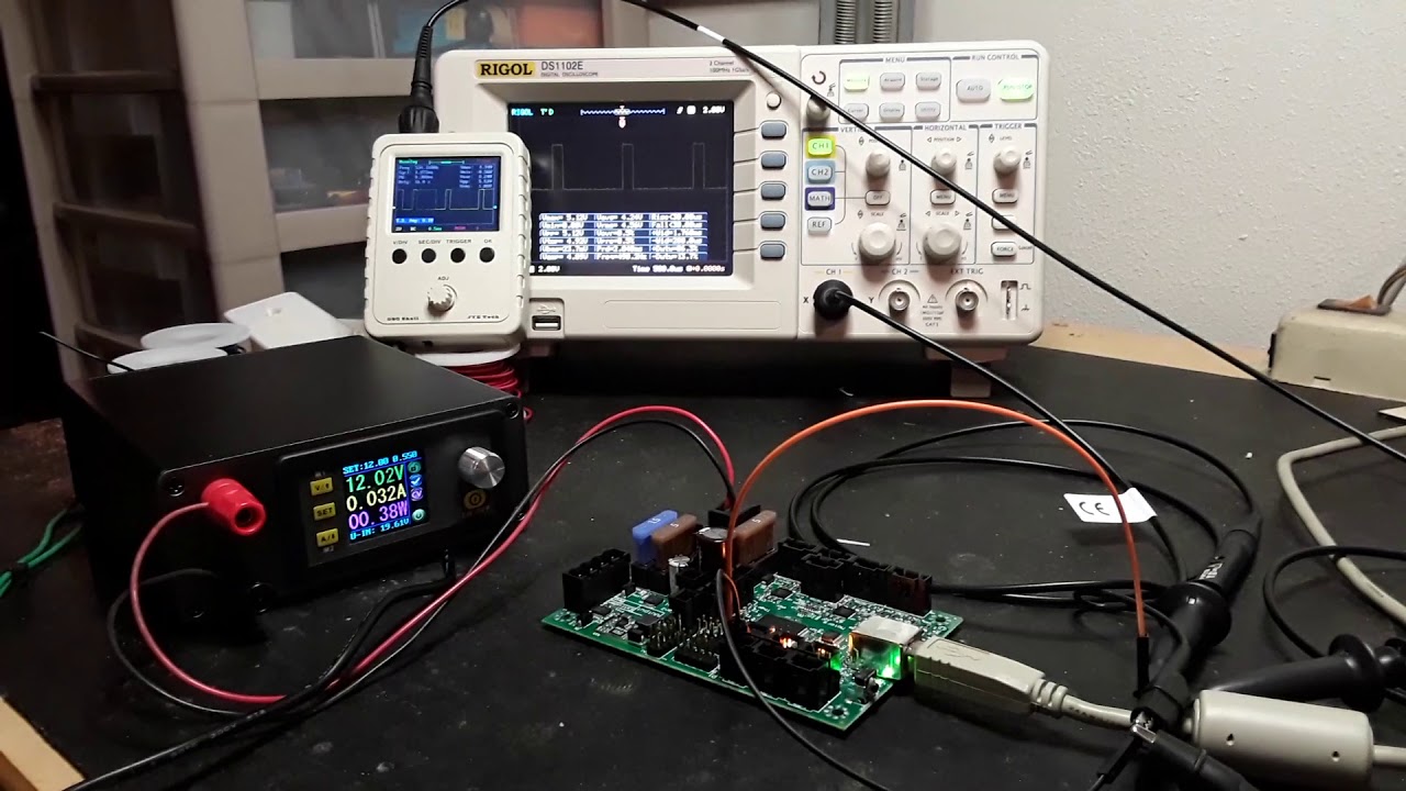
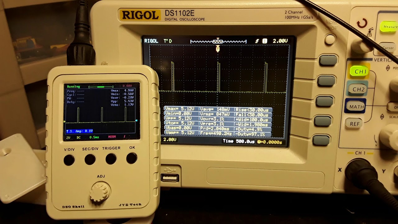
Jeff, the two short videos were showing the PWM period as 2 ms, so 500 Hz, for the mini-Rambo. And that matches what I was getting with the RAMPS. My MPCNC still uses all-thread and is using the old MPCNC813-GLCD firmware, with the D9 fan output remapped to pin 44. This setup has been running very well for a couple of years.
A recap from yesterday, as best I can remember… I tried so many things…
The mini-RAMBO… I couldn’t tell what firmware was flashed on it when I purchased it from Ryan a year or two ago. But since I needed to play with the laser and would be remapping things anyway, I downloaded the Marlin-MPCNC_MRambo_T8_16T_LCD firmware from github, got it compiled and flashed, and started probing around on the various pins while out on the work bench.
I spent the better part of the day looking about and reading, trying to find good information about where all the pins are physically located on the mini-RAMBO board and checking out signals with manual gcode input and the scope. I finally found the best information and schematics on the Reprap.org site, so I started playing around with both the FAN1/FAN2 outputs and the SPINDLE_LASER… stuff.
I did indeed play around some with the M03/M04 gcodes, which seemed to PWM the signals alright, but appeared “inverted”… with M03 S127 giving 50% duty cycle (DC) as you would expect but M03 S192 gave 25% DC, M03 S64 gave 75% DC, M03 S255 gave 0% DC, and M03 S0 gave 100% DC. I did exercise the Oxxx option a couple of times IIRC, and it varied the DC, but on the scope was indistinguishable from the Sxxx option. Also, what I’m calling the DC here is “time HIGH over the total period”. What I actually saw as described above, appeared to be “time LOW over the total period”… more an “active-low” vs “active-high” sort of thing.
Finally, I started playing with the FAN signals and see if I could duplicate what I saw with the RAMPS board… using the M106/M107 commands. I was finally able to get the FAN1 signal remapped to Z-MIN (the MIN signals are PWM pins, according to the compiler IIRC) and it seemed to exactly match what I’d seen on the RAMPS setup. This would also allow me to use the exact same Garfield file to test with…
So I slept on it and was pretty confident, this morning, that I could duplicate what I was getting with the RAMPS setup. But, no…
So that’s where I am now. I’m going to play around with it some more… now that I’ve got my teeth into it and can duplicate what Heath and Kelly have been seeing. I’m also reasonably confident now that I can remap signals/pins and handle compile errors when I see them. I am a bit bum-fuzzled about the mini- board not working as I expected it to, however. I’ll also probably hook the RAMPS back up and verify that it still works.
So, there you have it. I’ll keep you posted.
– David ,


