When I do things like this in Fusion 360, I import the mesh, then, in the Mesh workspace under Create, I used Create Mesh Selection Sketch. When creating this sketch, I’ll pick a point where fillets and chamfers are not caught. For example, for the feet I’ll move up about 5mm, so all I get is the outside outline and the slots.
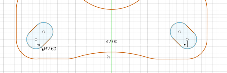
Next, I edit the sketch and either use 1) Create/Fit Curves to Mesh Selection, or 2) just redraw the geometry using the Mesh Selection Sketch as a reference. For the feet for the 25mm Primo I get the following:
I use Tinkercad to get cross-section drawings. If you import a mesh into Tinkercad, you can dowoad an .SVG of it. The drawing is a cross section of the object at the origin plane. (So for this, move the object down below the chamfers.)
At least using the fusion method, I don’t have to upload things…
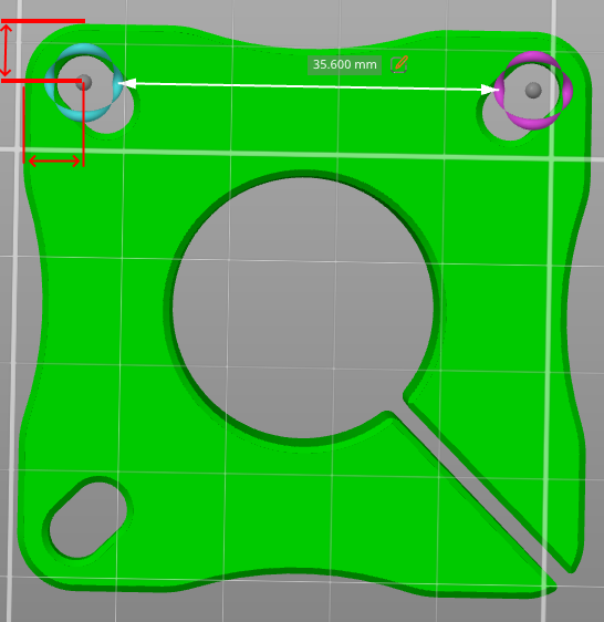
All this, however is perhaps moot in the case of laser cut steel… why not just cut a hole in the steel that you can fit the leg into and not use the 3D printed foot? I mean, the purpose of the part is to hold a piece of steel tube upright in a fixed position. Therefore the drawing of what you need is a 25mm circle. Given the information from Robert above, the center of that circle 26.5mm from the outer edges of your table. (1/2 of the 53mm dimension of the feet.)
Thanks for the Tinkercad trick. It would be nice to get an SVG to start so I don’t have to redraw the geometry, but I’ve had issues with the scale when bringing SVG files into Fusion 360…and the scale differences do not match any unit conversions I’m aware of. My SVG files have been from Lightburn, so the issue may be Lightburn specific.
The tinkercad SVG files use mm dimensions. Of course a mesh file won’t have proper arcs, they will all be straight lines, but I have found them useful for Fusion projects.